


October 29, 2014
The cable layout should be designed and a cable pulling plan developed, using the findings obtained during the site visit.
The proposed cable layout should be drawn on to an existing cabling diagram of the site if it is not a new site installation. The cabling diagram that is used should include all existing cabling and cable housings. For example, all cable trays, conduits and pole lines should be illustrated. For the purpose of orientation, it is essential to incorporate outlines of buldings, roads, and fixed machinery in the diagram. The new fiber optic cable routes should then be drawn over the top of this with a dark pencil. Termination cabinets and fiber node points containg splicing trays and patch panels should also be drawn on to the diagram in pencil.
A typical building cable network layout is shown i Figure 1. In some countries, according to their loacal fire prevention codes, outdoor cables that are filled with jelly should be spliced to non-flammable indoor cables close to the cable entries. Alternatively, the fibers can be cleaned and enclosed in protective sleeving ‘zero cable’, and taken to the patch panel or optical fiber distribution frame (OFDF) directly. The cross-connection arrangements and distribution hardware needs to be specified for each cable. In the market, there are many type of fiber patch panel, for example, 12 port fiber patch panel, sc fiber patch panel, 16 port patch panel and so on. Our store offer you different types fiber optic patch panel to the customers, now we will introduce two hot sale types in our store.
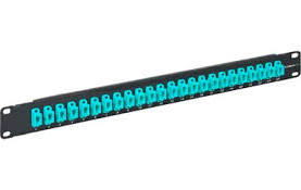
This Blackbox patch Panel secures 12 breakout modules in the horizontal or zone distribution areas. It features a low profile that requires little wall space, as well as a large routing space for accessible patch cabling entrance. Top and bottom grommet holes provide easy entrance for the horizontal trunk cables. Incorporated spool rings can secure and store excess cable lengths with a safe bend radius.
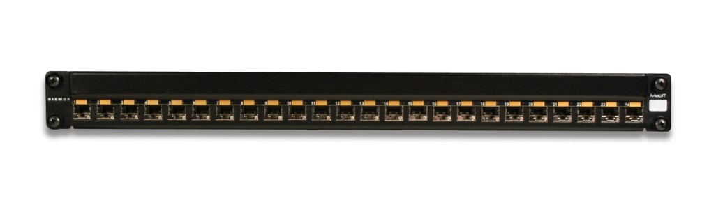
With this High Density 24 port patch panel, you can easily make one rack unit support your 10GB or higher applications. They allow you to quickly add new devices to your system without having to manually install or reconfigure other devices. The fiber is routed and connected on the inside of the cassette. There is no cutting, polishing, or terminating. These patch panels are perfect when you have high fiber count installations.
Figure 2 illustrates a typical cable layout diagram. Note that the diagram includes the cable fiber sizes (the number of strands in the fiber) to be installed, the locations for new and old pit boxes, the requirement for new conduit and for fiber optic termination cabinets.
If a fiber ring is being formed, the cables are normally cut in the pit, both ends are taken into the building where they are either spliced through or pig-tails are connected to the fibers before taken to a fiber optic patch panel 24 port. Often, there is combination of spliced fibers (which are more secure compared to those on a patch panel) and fibers with pig-tails taken to a patch panel. Taking them to a fiber patch panel allows the rings to be made or broken as required, but leaves them free to accidental removal. Compare the length of each cable run with the length of fiber optic cables on the reels that are to be used. Using this information, determine the location of any additional intermediate splicing locationg that are required.
Once the cable layout diagram is complete, a cable installation program should be drawn up. This document will be used by the contractor’s installation procedures and requirements. It should contain a thorough description of all the considerations and potential problems that were noted during the site survey.
The installation program should include a detailed description of the following information:
â— The logistics of pulling the cable.
â— Where the pulling equipment and cable reels should be located during the installation for each separate pull.
â— The precise location where the pit boxes, termination cabinets and splicing trays are to be located.
â— Which fibers are to be spliced and which fibers are to be taken through to a patch panel
â— Each separate cable pull and the cable size and type to be pulled.
â— Each separate conduit installation and the size and type of conduit
to be installed. Specify which conduit is to be used over each section.
â— Which cable trays are to be used.
â— The routes to be taken for cable runs through the roof space.
â— All the cable trays, conduits or other housings that will need replacing.
â— An installation schedule that would minimize traffic congestion while carrying out road works during peak hours.
◠The setting up of ‘no parking’areas where installation equipment is
to be located. This should be carried out the day before the
installation begins. This requirement should cover all pit boxes and
manholes.
â— All observations that were made during the site visiit.
â— The specific responsibilities of each member of the installation team should be defined.
When the installation is complete, document all the changes made during the installation and produce final‘as installed’drawings. This will help to ensure that the cables have been installed correctly and that future fault finding and any system upgrades will be hassle free.
Article Source: Fiber optic components blog
Posted by: kelonlau at
09:06 AM
| No Comments
| Add Comment
Post contains 899 words, total size 8 kb.
October 16, 2014
Almost everyone are aware of a SFP transceiver. The idea of SFP as well as THEM area get a detailed association against each other. SFP is the word for Gigabit Slot Convertor. Thus technologically engaging, Copper SFP Devices is definitely put in place in a fashion that would probably vary if there are actually serial electronic information within serial optical information. In combination with almost all these, a Ciscos will be along with your multi-level turn this one-way links a Roughage Optic together with the Ethernet procedure. The following has become the a lot of embraced towers to get SFP Ciscos will be Gigabit Ethernet plus Roughage Siphon.
Now, prestigious repair shops with SFP transceiver as well specialise in Cisco SFP plus Cisco transceivers, coupled with SFP supplement different versions plus methods. Additionally deliver OEM like-minded Finisar FTLF8519P2BNL and give tailor-made ways to its purchasers to get any specific leading-edge demands. While in the developing step, all these institutions make an effort to wipe out a lot of wasteful tactics. Hence, other than caterers plus reaping helpful benefits, additionally work at a nutritious ecosystem
Your transceiver is actually a specialised mixture of wr plus transformer. Organizations specified enhancements in such a arena with transceiver plus optical roughage. SFP is definitely popular pluggable plus rendering it effortless add and it's bendable around design. Them has become the a lot of critical issues to get optical transceivers. Also, also, it is competent to aid a number of natural media channels such as, with the legacy photographer so that you can extensive send solo style roughage and assend to varied miles.
Posted by: kelonlau at
07:00 AM
| No Comments
| Add Comment
Post contains 276 words, total size 2 kb.
October 09, 2014
XFP transceiver are meant running some sort of mode connected with facts of up to 10 Gigs (Gigabits) and are also modest style issue sizzling pluggable transceiver. AGM732F are a very little small and have absolutely some sort of capacity for 5 Gigs connected with facts, doing these individuals far more effective intended for small communities and even more appropriate for property apps, as an alternative to small business locales. There are various different transceiver in addition to ingredients included in Ethernet technological know-how, in addition to there are various corporations of which created excellent items that usually are simple mount in addition to work with devoid of an excessive amount stress.
Fully best with almost all equipment out there, FTRJ8519P1BNL is usually paired having turns or maybe routers to help take full advantage of ones Ethernet network in addition to assist you gain by far the most reliable, stable mode connected with facts you can use. With a lot of cases, this transceiver are often swappable and once you end up picking another transceiver, it would be fitted with a few minutes, subsequently many you should do is usually be connected ones Ethernet cable connection in addition to you will be wanting to return to do the job, far more fruitful than any other time.
The obvious way to show you it is which has a PCI cards just a computer system of which provides to be a coordinator intended for SFP transceiver. This transceiver independently is usually substituted, in addition to as time goes on, this cards per se is usually swapped out in the event important. That affords the most current really advanced Cisco GLC-T transceiver for being utilised in addition to the substitutes down the line devoid of being a bunch of money. Trying to keep this programs small is significant mainly because living space is confined, as well as a facts core of which channels a significant bit on the World-wide-web to help it is a variety of areas may not need infinite living space.
Posted by: kelonlau at
06:23 AM
| No Comments
| Add Comment
Post contains 344 words, total size 3 kb.
October 06, 2014
Digital camera amplifiers usually are alternatively traditionally used of late along with try a digital camera electrical power portion pertaining to amplifying your indication. High Power EDFA are likely to be additional useful in contrast to a number of amplifiers pertaining to sound system, your audio good quality can often be just about as good. Due to innovations throughout amplifier technological innovation, essentially the most up-to-date digital camera amplifier varieties occur close up regarding audio distortion thus to their analog alternate options. Class-D amplifiers get began for you to take the place of Class-A plus a variety of amplifiers as an illustration tv amplifiers. To deliver a sample, nearly most home cinema AUDIO-VIDEO receivers incorporate digital camera amplifiers.
Even though deciding on the music amplifier, one of several principal problems will probably be your amplifier electrical power. In situations where you are adding your current sound system in a rather significant place and then not simply does one have to have a number of rather major sound system and also an audio amplifier which in turn are able to travel your current sound system sufficiently high in volume. Every time you will need to manage your current amp within a reasonably smaller place, it is not necessary plenty of wattage. Actually, EDFA might be a great deal. You'll find a pair of ways to support specify amp wattage. Your RMS electrical power associated with an amplifier details precisely how much wattage your amp could consistently present although the absolute maximum electrical power demonstrates the amount your current amplifier could produce within just a brief time period of your energy.
While deciding on the amplifier, most of the people commonly take into account the amp features. Your wattage associated with an amp can be amid these kind of features. The larger the electricity your more noticable could your amplifier travel your sound system. Pertaining to humble spots, conversely, you possibly can purchase the amplifier which in turn gives at most 30 M involving wattage. Recognize, however, you'll find only two conferences when considering calibrating your amplifier wattage. Your RMS wattage associated with an amplifier will be the nearly all fair normal. It indicates the best way very much electrical power your amplifier may present in a expanded time frame. Conversely, the absolute maximum amp electrical power shows the amount electrical power your amplifier may produce by having a simple break open of your energy. Your RMS electrical power is commonly superior in relation to compairing a variety of audio amplifiers in contrast while using optimum wattage. That may be since there is not any normal in relation to calibrating your optimum electrical power associated with an amp. For that reason, many amplifier makes will certainly overstate your features with their individual solutions.
Posted by: kelonlau at
06:23 AM
| No Comments
| Add Comment
Post contains 468 words, total size 3 kb.
32 queries taking 0.1577 seconds, 64 records returned.
Powered by Minx 1.1.6c-pink.

