


July 30, 2014
 Many product portfolio using a small cellular hardware device, that's made to result in the wireless network providers to raised network data for growth analysis and monetization, Cisco said, "this might make the mobile network data to get better." The data from 3G, 4G and WiFi network, reaches mobile or fixed network connection, real-time data generated among users.Based on Cisco said, this season to 2017, mobile data traffic will grow 13 times. By 2017, you will observe devices to gain access to network, including cell phones and machine to machine communication connection.Using Quantum software, wi-fi providers possess a more profound knowledge of their own network of knowledge, to be able to obtain better network programmability, and network service quality. Providers can abstraction and research to the data better, to provide users with satisfactory service, and grow their own 3G, 4G, WiFi and small cellular hybrid network.Quantum network abstraction suite Quantum software within the product mix, might have towards the company to have an instant a network abstraction layer, enabling it for the collection of data within the network, as well as the data were gathered and coordination; Quantum strategy kit could be a measure for providers, network regardless of the sort of server management, monetization and customization platform; Quantum analysis suite allows providers more conveniently using the real-time data and historical data to build up strategies, which supplies visualization analysis and programmable interface; wide area network coordinated suite provides a convenient control over network traffic along with the capacity from the tool for providers, to boost the network efficiency, reduce the cost of.Cisco cellular hardware small should better accessibility network, it will help such as Verizon wireless carrier and AT&T wi-fi providers to facilitate the introduction of its network.Additionally, Cisco may also exhibit ASR 901S router inside the MWC exhibition. Obviously, if you would like Cisco GLC-lH-SM SFP, you are able to follow the link.MWC: Cisco displays the hybrid wireless network products.
Posted by: kelonlau at
10:01 AM
| No Comments
| Add Comment
Post contains 406 words, total size 3 kb.
July 29, 2014
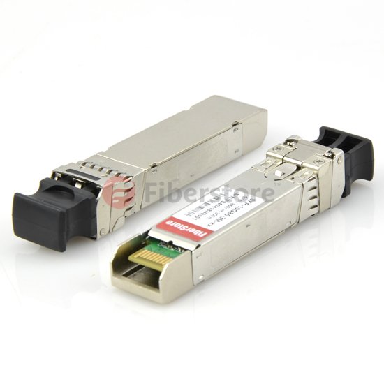
The Cisco SFP transceivers are designed to change the serial electric signals to the serial optical signals which mainly maintain gigabit Ethernet, includes fiber channel and SONET/SDH, it provides a beneficial way, adopt the method of resolution in the university campus, data center, metropolitan areas, ring networks and store web site.
Ethernet converter net from one end to another in order to let more systems with different thread accurately corresponding associated Ethernet cable. This is likewise being used within the similar set up once there are several computers functioning with varying types of technology. In addition, optical fiber cable can defy from any type of electronic equipment, mobile phones and wireless complex which usually don’t like with the traditional Ethernet, such equipment which was exposed loses the signal interference. In this case, as converted into optical fiber Ethernet, because it provides a quick and excellent signal. The SFP is by the maritime safety administration or from IBM, lucent, Siemens, ample/TYCO and Infineon Multi-source is unqualified, this is the main content of the network vendor management. The SFP transceivers have the following advantages:
1. For reasons of that you can insert, optical fiber interface, still can modify on the end pace of the creation of the card.
2. It is able to accommodate a lot of connector interface or a combination of LX SFP and SX.
3. Since the basket of SFP transceiver is placed in the PCB in order to accept stated, it can reduce the additional program, thereby reducing the costs. As a result, it made it easier to reconfigure and replacement.
4. Because of optical element, SFP transceivers enhanced reliability. It allows the use of higher the temperature.
Cisco SFP is interchangeable, in addition to its flexibility, from a wide range of Cisco project. It can be used with Cisco 1000BASE-TX, 1000BASE-SX, 1000BASE-LX/LH, 1000BASE-EX, 1000BASE-ZX, or 1000BASE-BX10-D/U in a port through the port joint.
Cisco SFP modules need to connect the one-piece structure to another, because it plays an important role in the most commonly used information technology business.
The SFP transceiver modules are generally hot-pluggable I/O devices that can easily get plugged into the module sockets. The transceiver efficiently connects the electrical circuitry of the module to the copper or optical network. Users can utilize any combination of SFP transceiver modules that the Cisco transceiver device assists. The only thing to take note here is that every port should match the wavelength requirements on the other end of the cable and that the cable should not exceed the concerned cable length in order to ensure consistent communication. It is recommended that users utilize the SFP transceiver Cisco modules only on the Cisco instrument. Every single Cisco SFP transceiver module assists the Cisco quality identification that enables a Cisco router or switch to identify and authenticate that the transceiver module is examined and approved by Cisco. Now I introduce SFP-10G-ZR compatible with Cisco devices in Fiberstore. it is cheaper than Cisco company. The SFP-10G55-80-CO series single mode transceiver is small form factor pluggable module for duplex optical data communications of 10G. This transceiver offers the same function with Cisco SFP-10G-ZR and it is fully compatible with Cisco devices. It is with the SFP+ 20-pin connector to allow hot plug capability.This module is designed for single mode fiber and operates at a nominal wavelength of 1550 nm.
Fiberstore was founded in 2001, our focus is to provide high quality fiber interface, SFP compatible modules, GBIC LAN and WAN networks and related products. Fiberstore believes that the road to success is through excellence and customer service. And now Fiberstore in order to feedback customer of their comings, it is making with 30% discount of the price, it you want know more information about these fiber optical transceivers welcome to visit our Fiberstore.
Article Source: http://www.fiber-optical-networking.com/
Posted by: kelonlau at
06:28 AM
| No Comments
| Add Comment
Post contains 641 words, total size 5 kb.
July 25, 2014
Today's Data Centers are critical to the IT infrastructure of most large enterprises. Thanks to their quick-connect design, Plug-n-Play (PnP) fiber systems are becoming the prevalent choice for modern Data Centers. With Plug-n-Play, installation is fast and easy, and network downtime is minimized during expansions, scheduled maintenance, and emergency restoration procedures.The mainstays of modern PnP Systems are the relatively new multi-fiber connectors that allow for the interconnecting of several fibers at a time in a very dense footprint.
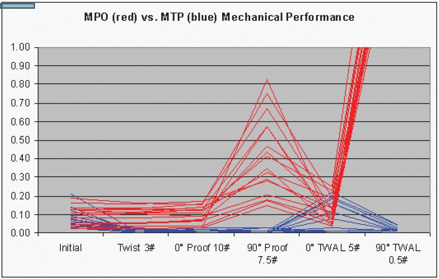
MPO stands for "Multi-Fiber Push On†and was originally designed by NTT. The design is based on the MT (mechanical transfer) ferrule. It is defined by the Telecommunications Industry Association's (TIA) Fiber Optic Connector Intermateability (FOCIS 5) document, the TIA 604-5B Standard, and internationally by the IEC-61754-7 standard. The MTP connector is the "latest-generation MPO†connector with flaws fixed and features added in order to improve reliability and performance. Some improvements include lower insertion loss, the possibility of restoring the tip by polishing it and the use of interferometers for better quality control(2).The MTP's superior performance allows for optical insertion losses of 0.5dB or less. Figure 1 shows superior mechanical test performance results, another of the clear advantages of the MTP connector.
Both connectors are intermateable, meaning it is possible to connect an MTP to an MPO and vice-versa. Each connector will support a number of fibers, the most common being 12, while some versions are available with 24 fibers or even more. However, one should consider whether the space savings and easy connection convenience provided by connectors terminating more than 12 fibers will potentially impact reliability. Servicing a single fiber that may have been damaged will require the disconnecting of all other fiber channels linked through that connector. MTP and MPO connectors have guide pins to ensure proper fiber alignment and minimize optical insertion loss.These pins are present on the "male†connectors only. However, MTP connectors can be easily converted from "male†to "female†by removing the pins and, conversely,"female†to "male†by adding the pins.
Fiberstore has announced the release of a full suite of MPO MTP products designed to support the next generation of high-density fiber networks in data centers. The new product group includes MPO MTP Fiber Optic Cables, trunk assemblies, fan-out assemblies and related distribution hardware.
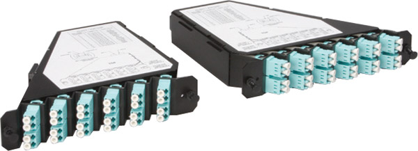
Fiberstore series rackmounted patch panel is designed to manage and house easy-plug MTP/MPO to LC fiber cassette modules, for connecting plug-and-play pre-terminated high density MTP / MPO Fiber cabling system.This solution contributes to greater network availability that especially suitable for SAN, LAN and Data Center applications. Each easy-plug MPO MTP cassette is accommodated with a 12/24-fiber MTP / MPO based fiber assemblies, and pre-loaded with LC adapters in different fiber modes for your choices.
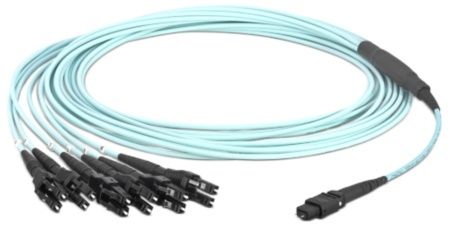
Fiberstore High Fiber Count Plug-and-Play Trunks provide the backbone cabling for the TrueNet Plug-and-Play system. These high count fiber trunk cables come pre-terminated with highdensity MTP/MPO connectors on both ends and provide an easy and efficient way to pull large numbers of fibers at one time to help in the rapid deployment of the TrueNet Plug-and-Play system either in the data center or Local Area Network (LAN). Each fiber trunk cable has custom breakouts designed to work with ADC TrueNet Plug-and-Play connectivity. The Fiberstore High Fiber Count Trunks can simply be plugged into any plug-and-play cassette in the optical distribution frame or fiber enclosure which eliminates the need for on-site fiber termination and preparation. Data Centers host expensive equipment and process very sensitive information for networks that must be always available.This level of reliability imposes stringent requirements on a Data Center's infrastructure. A Data Center manager must be able to quickly perform adds, moves, and changes, as well as restorations in case of an outage. A very good analogy is a racecar making a pit stop and being serviced as quickly as possible. In a data center hosting mission critical applications, every second also counts. Therefore, the ability to quickly connect new equipment or service existing equipment is crucial. To accomplish this "quick-connect†capability, the fiber optics industry formulated a new de facto fiber standard, sometimes referred to as "Plug-n-Play†(PnP), based on an existing philosophy already adopted by many vendors in the computer industry. PnP systems are based on trunk cables, cassettes, harnesses, etc, which are comprised of pre-connectorized fiber optics elements.
Another solution for achieving quick connection is the use of multi-fiber connectors. By connecting several fibers at once, the installer or administrator saves a considerable amount of time. Since the time to connect a 12-fiber MTP connector is the same as to connect a single fiber connector (also called a discrete connector) one can make the same number of connections in roughly 1/12th the time. A common data center can easily reach 1,000 fiber terminations or more. Consequently, the time-savings can be significant. Because PnP systems also allow for pre-engineered solutions, it is possible to determine cable lengths during the planning phase and, therefore, order only what is needed.This not only helps saving money on fiber infrastructure but also helps to alleviate cable congestion under the raised floor. Since one of the main issues data center administrators have to face is cooling increasingly dense computing infrastructure, the use of a preengineered PnP system also helps to optimize cold air distribution. As previously mentioned, the building blocks of a PnP system are cable trunks, harnesses, PnP modules (often called cassettes), patch cords (also called jumpers) and accessories such as patch panels and enclosures. Multi-fiber connectors are present in virtually all these elements, and, along with small form factor connectors such as the LC, allow for reducing the "real estate footprintâ€in the data center.A solution using MTP and small form factor connectors can be almost twice as dense as a solution using previous generation optical connectors.Therefore, more floor space is left available for mission-critical equipment such as switches, routers, servers and storage.
Posted by: kelonlau at
06:28 AM
| No Comments
| Add Comment
Post contains 983 words, total size 7 kb.
July 24, 2014
MPO/MTP system solutions are steadi-ly gaining in significance. Data centers in particular have a great need for compact and flexible plug-and-play systems that are pre-measured and preterminated at the factory. MPO/MTP system solutions allow users to achieve complete end-to-end cabling in keeping with the new standard for data centers. In the IEEE 802.3 standard, 40 Gb/s and 100Gb/s were defined with MPO connector technology. The crucial factor is the insertion loss and return loss of the components. Controlled production processes and ultra-precise end-face geometry are needed to satisfy these tough requirements. With the MPO/MTP multi-fiber system, a data center is well-equipped for future transmission rates of 40 and 100Gb/s.
Benefits of deploying modular, high-density optical solutions, such as MTP-based connectivity (including MTP Fiber Optic Cables assemblies, breakout modules and breakout harnesses) in a structured wiring architecture include 50% cable-tray space savings, 80% improvement in deployment time, and 70% bulk-cable reduction in cabinets and racks. A modular, high-density solution deployed in a structured wiring topology can easily scale to hundreds of thousands of ports and significantly reduce the time to conduct MACs in the data center, thus reducing operational costs.
So now, we have the means to cope with future growth and churn in the data center. Now, let’s address the issue of keeping this modular high-density structured cabling system in place to handle future higher-data-rate applications. In addition to manageability and scalability, a benefit to deploying a modular, high-density MPO-based cabling system is the available migration path to increased data rates. With some consideration of performance specifications, the infrastructure can easily migrate to future higher-data-rate technologies, such as parallel optics, which will be used in 32-, 64-, and 128-Gigabit Fibre Channel; and 40- and 100-Gigabit Ethernet. In fact, by deploying an optical cabling system that meets InfiniBand 12X-QDR (120-Gbit) cable skew performance requirements of = 0.75 ns and distance specifications, the same infrastructure that is carrying serial transmission today can be easily migrated to transmit parallel-optic InfiniBand signals.
To mitigate this issue and increase the lifecycle of an optical-cabling infrastructure, deploy high-quality low-loss optical components. Low-loss MPO Fiber Trunk Cable, breakout harnesses, modules and jumpers minimize channel insertion loss and enable the cabling infrastructure to easily migrate to future higher data rates.
For example, 8-Gbit Fibre Channel will support a distance of 100 meters using OM3 fiber and a connector budget no greater than 2.4 dB. If an MPO mated pair has a maximum insertion loss of 0.5 dB, and each MTP-to-LC breakout module wasspecified at a maximum insertion loss of 0.75 dB, then theresulting maximum connector loss in the channel will be 2.75 dB. This exceeds the recommended maximum 2.4 dB connector loss budget of 8-Gbit Fibre Channel at 100 meters, thereby reducing the supportable distance at 8-Gbit Fibre Channel; however, if low-loss components were specified into the same cable plant at 0.5-dB maximum insertion loss per MTP-to-LC breakout module and 0.35-dB maximum per MTP mated pair, then the resulting maximum connector loss in the channel will be 1.85 dB, providing support of 8-Gbit Fibre Channel beyond 100 meters.
As previously discussed, TIA-942 addresses the use of ZDAs as part of the recommended topology for datacenters. Implementing a distributed zone solution reduces pathway congestion and facilitates the implementationof MACs common in the data center environment. Implementing a zone topology can increase the number of connection points in a given channel. Using components with low-loss performance enables zone connectivity without sacrificing distance capabilities due to channel insertion loss. Additional methods to implement zone distribution with reduced channel insertion loss include using components that are optimized for the architecture. Solutions that offer a combined MPO-based trunk assembly and breakout module can eliminate connector pairs while still offering the flexibility of zone cabling, thereby reducing total channel insertion loss. Now we introduce some MTP/MPO assemblies when you are solving MTP/MPO system.
MTP high density cabling solutions utilizes MPO (multi fiber push on) ferrule providing connection of 12 or 24 fibers. MTP provides superior physical and optical characteristics than standard MPO for precision alignment with spring loaded mechanism and guide pins. They have a removable adaptor that mates female connectors to a male connector with specially designed guide pins for orientation and maintaining polarity along the channel. The Micro-core cables used in factory terminated MTP fiber cable assemblies give 65% reduction in cable size from traditional fiber cables. Pre-connected MTP solution with 24 core LC duplex adapters offers 72 LC terminations in 1U rack space and 288 LC terminations in 4U rack space using modular patch panels.
MTP Patch Panels are scalable modular which are designed for high density Gigabit Ethernet Applications.They are used for terminating backbone cables at the Main Distribution Area (MDA) and Horizontal Distribution Area (HDA). MTP Patch Panels are available with 1U and 4U, suitable for standard 19†racks. 1U MTP Patch Panel can accommodate up to three MTP Cassettes, giving a high connectivity of 72 LC fiber terminations in it. 4U MTP Patch Panel can accommodate up to 12 MTP Cassettes, resulting in a maximum of 288 LC terminations per panel.
Fiberstore offer a wide range of MTP/MPO product including MTP and MPO trunk cables, MPO and MTP cassettes, MTP and MPO harness (breakout) cables. MTP/MPO Cable assemblies are fully compliant with IEC Standard 61754-7 and TIA 604-5. All MTP and MPO assemblies can be customize. More details, please call us or send an email to our customer services.
Posted by: kelonlau at
08:04 AM
| No Comments
| Add Comment
Post contains 912 words, total size 7 kb.
July 17, 2014
As enterprises implement more fiber optic cabling to support bandwidth and storage requirements in the data centre and backbone infrastructures, fiber termination methods are under intense scrutiny. Data centre managers need to understand the key performance, installation, management, and cost considerations surrounding primary fiber termination methods. Each method has its own pros and cons, and the need has never been greater for comprehensive information to help data centre managers make the right choice for their environment. In this white paper, you will learn the about the pros and cons of the following fiber termination methods:
•Preterminated Plug-and-Play MPO Solutions
•Factory-Terminated Pigtails with Splicing
•Field Termination
The MPO connector is a high-density, multi-fiber connector that typically terminates 12 fibers in one connector approximately the same size of a one SC-style fiber connector. MPO Cassette include an MPO interface on one side broken out to12 individual fiber interfaces on the other side. These cassettes can be deployed in an optical distribution frame for higher density applications or in fiber panels to connect the main distribution area (MDA) to the equipment distribution area (EDA) in the data center. Plug-and-play trunk cables are round 12-fiber cables that are preterminated in the factory with MPO connectors on both ends. These trunk cables are purchased in predetermined lengths and are typically easier to manage than traditional ribbon cables. They can be quickly connected to the MPO plug-and-play cassettes at the cross-connect or interconnect in the MDA, EDA, or other areas of the data centre. This method eliminates the need for on-site fiber termination and splicing. Consequently, customers can rapidly complete fiber connections in high-density applications.
Advantages to plug-and-play MPO solutions include:
• Reduced Labor Cost
Less time is required for plug-and-play installation vs.splicing or
field termination. Less expertise and resources are required of
installation staff.
• Enhanced Performance
MPO connectors are
factory terminated and tested in a clean environment with comprehensive
quality control processes and documented test results that correspond to
serial numbers stamped on each assembly.
• Better Manageability and Density
MPO cassette offer the highest density for fiber connections, maximizing space
savings in the data centre. They are easily deployed in a cross-connect
scenario for better cabling management.
• Better Prepared for Beyond 10-Gigabit
40-Gbps and 100-Gbps speeds on multimode fiber will likely require parallel optics where data is transmitted and received over multiple fibers. MPO connectors are more prepared for this technology because they already encompass multiple fibers.
Disadvantages to plug-and-play MPO solutions include:
• Inreased Material Cost
Plug-and-play MPO solutions are typically more expensive than other options.
• Higher Return Loss and Insertion Loss
The additional mated pair increases the return loss and insertion loss. Insertion link loss with MPO solutions can account for an addition 0.5dB per cassette, requiring careful planning of the loss budget.
• Limited Access to Individual Circuits
With MPO Fiber Trunk Cable, individual circuit access to backbone cabling is limited. However, when used in a cross-connect scenario, individual circuits should not need to be accessed once installed.
• Pedetermined Lengths Required
MPO trunk cables are made to order in predetermined lengths, so lengths and lead-time must be part of the planning process. In addition, measurements need to be exact or slack storage will be required.
Fiberstore MPO Cassette provides seamless plug-and-play structured cabling solution especially suitable for high density data center environment. By integrating with Fiberstore Plug-and-play rackmount enclosure, it connects between the MPO interfaces on the backbone trunk cable to the generic LC interface that will directly link to the equipment.
The cassette is designed with a user friendly snap-in modular style, pre-installed with factory-terminated and factory-tested 12- or 24-fiber MPO to LC assembly with assured best performance on optical loss. The convenient plug-and-play feature offers a flexible, quick-deployment solution with maximum reliability and durability, which offers a simple and efficient choice in optimizing your network system.
Fiberstore manufactures a wide range of MTP/MPO products including MPO/MTP fiber cables, MTP/MPO Harness Cable, MTP/MPO trunk cable, MTP/MPO cassettes. Multi fiber ferrule connections used in high-density backplane and Printed Circuit Board (PCB) applications in data and telecommunications systems. High density MTP/MPO trunk cables with up to 144 fibers. The MPO Cable connector offers up to 12 times the density of standard connectors, providing significant space and cost savings.
Posted by: kelonlau at
07:25 AM
| No Comments
| Add Comment
Post contains 716 words, total size 7 kb.
July 14, 2014
When moving to 40/100GbE, the most important difference in backbone and horizontal multimode applications is the number of fiber strands. 40GBASE-SR4 uses 4 strands to transmit and receive for a total of 8 strands. 100GBASE-SR10 uses 10 lanes to transmit and receive for a total of 20 strands. SMF remains a 2-strand application and although the fiber is less expensive, SMF optics and electronics can be 10x more expensive. In data centers and backbones, it may be possible to have 8 or 20 individual strands of fiber. However, those strands may take disparate paths from one end to the other and this can cause delay skew (known as bit skew) resulting in bit errors. For this reason, the 40/100GbE standards are written around fiber optic trunk assemblies that utilize a MPO or MTP multi-fiber array connector. In these assemblies, all strands are the same length. Also referred to as "parallel optics," this construction minimizes bit/delay skew, allowing the receive modules to receive each fibers information at virtually the same time.
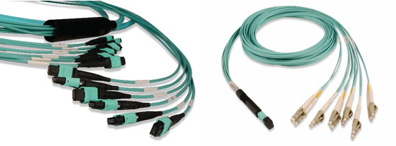
MPO (Multi-fiber push-on) and MTP (Mechanical Transfer Push-on) are available in both 12 and 24 strand termination configurations used at the end of a trunk assembly. The MTP design is an improved version of the MPO Cable. The patented MTP connector is a ruggedized version with elliptical shaped, stainless steel alignment pin tips to improve insertion guidance and reduce guide hole wear. The MTP connector also provides a ferrule float to improve mechanical performance by maintaining physical contact while under an applied load. MPO MTP trunks also support for the 10GBASE-SR/SX applications although only two fiber strands are used. In this case trunks are connected to cassettes and/or hydra assemblies, which break out the multiple fibers into two-strand connections (typically LC or SC).
The second difference in high-speed fiber configurations is polarity. For 2-strand applications such as 10GbE transmission, managing polarity is as simple as reversing the strands somewhere over the channel. This is true if the channel is constructed of individual strands or is part of a trunk assembly. In trunk assemblies, which have historically been 12-strand, there are three suggested polarity methods in the standards (as shown in the following table).
As shown above, 2-strand application polarity managing is relatively easy. When migrating from 2-strand to multi-strand parallel optics, it is important to note which polarity method was selected to assure that the correct assemblies are purchased for higher speeds. All polarity methods can be converted from 2-strand to 12-strand applications.
It is important to note that these polarity methods are suggested in the standards, not mandated. However, the mandate does state that a polarity method should be established and maintained throughout all fiber channels, mapping the transmit strand from one end to the receive strand at the other. This does not change for higher fiber count transmissions, with the exception that more strands are involved. To better visualize the transmission for multistrand applications, consider the following diagrams:
40GBASE-SR uses 8 strands of a 12-strand MPO/MTP Fiber Trunk Cable, (4 to transmit and 4 to receive). The middle 4 strands in the MPO/MTP connector remain dark. The interface on equipment will accept an MPO/MTP array connector rather than a traditional LC.
100GbE has three approved methods for transmission including one 24-strand (shown left) or two 12-strand trunks either "over and under" or "side-by-side" (shown right- Side-by-side configuration is not shown). The transmission uses 10 strands to transmit and 10 to receive leaving the outer unused strands dark. It is also possible to connect two 1- strand trunks via a "Y" assembly that converts two 12-strand trunk assemblies to one 24-strand assembly. Polarity must also be considered regardless of the method chosen and supported by the electronics.
The new MTP cables can bridge legacy 1Gbps/10Gbps networks over to 40Gbps/100Gbps networks, and can act as the trunk line on a network backbone. Since a single fiber cable can connect up to 24 devices, fewer cables are needed, cutting down on installation labor. The high-density, small form factor also saves space and improves air flow. With its push-pull release mechanism, the MTP connector is easy to engage and disengage.
FiberStore provide a wide range of MTP/MPO products including single mode or multimode MPO and MTP fiber cable. High density MTP/MPO trunk cables with up to 144 fibers in a single cable. Fiberstore also offer wide range of MTP MPO cassette. The standard cassettes can accommodate 12 and 24 port configurations. Different sizes of cassettes are available. Available in all fibermodes and connector options. Custom Options available including MPO MTP taps and MTP/MPO Silitter combinations.
Aritcle source from: http://www.cables-solutions.com/fiber-transmissions-at-higher-speed-ethernet.html
Posted by: kelonlau at
07:19 AM
| No Comments
| Add Comment
Post contains 772 words, total size 6 kb.
July 09, 2014

With the length and type of the fiber cable and number of connectors and splices all contributing to the link loss, data center managers are faced with the challenge of calculating each connection point and segment within their fiber channels. Multi-fiber push on (MPO) or mechanical transfer push on (MTP) connectors are rapidly becoming the norm for switch-toswitch connections due to their preterminated plug and play benefits and ease of scalability from 10 to 40 and 100 gigabit speeds. Unfortunately, typical MPO MTP module insertion loss may not allow for having more than two mated connections in a fiber channel, which significantly limits design flexibility and data center management. Low loss, rather than standard loss, MPO/MTP connectors better support multiple mated connections for flexibility over a wide range of distances and configurations while remaining within the loss budget.
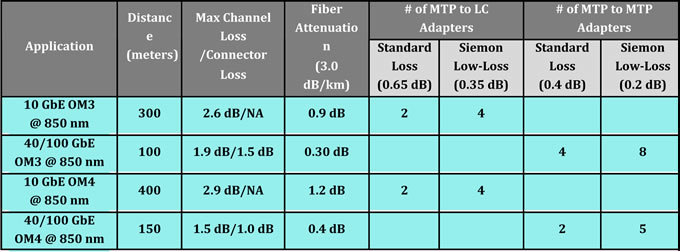
Typical MPO/MTP connectors, which are required for 40 and 100 GbE eployments have insertion loss values that range from 0.3 dB to 0.5 dB. Typical LC multimode fiber connectors have loss values that range from 0.3 dB to 0.5 dB. While better than the allowed 0.75 dB TIA value, typical connector loss still limits how many connections can be deployed in 10, 40 and 100 GbE channels. For example, with an LC connector loss of 0.5 dB, a 300-meter 10 GbE channel over OM3 fiber can include only three connectors with no headroom. Having just two or three connections prevents the use of cross connects at both interconnection (MDA) and access switches (HDA).
Due to improvements in connector technology and manufacturing techniques, Fiberstore has succeeded in lowering the loss to 0.20 dB for MTP connectors and to 0.15 dB (0.1 dB typical) for LC and SC connectors, well below the industry standard of 0.75 dB and loss values offered by other manufacturers.
For 10 GbE, Fiberstore low loss LC fiber jumpers offer a loss of 0.15 dB (typical 0.1 dB) and Fiberstore low loss plug and play MTP to LC or SC modules offer a loss of 0.35 dB (typical 0.25 dB). For 40 and 100 GbE, MTP to MTP pass-through adapter plates and MTP fiber jumpers offer a loss of 0.2 dB. These lower loss values allow data center managers to deploy more connection points in fiber channels, enabling the use of distribution points or cross connects that significantly increase flexible configuration options.
Figures 6, 7 and 8 shows some example scenarios for deploying cross connects in 10 GbE and 40/100 GbE channels over OM3 and OM4 fiber using Fiberstore low loss fiber connectivity. In Figure 6, all changes are made at the cross connect with LC fiber jumpers. The switches remain separate and the permanent MTP trunk fiber cables need only be installed once. The cross connect can be placed anywhere within the channel to maximize ease of deployment and manageability.
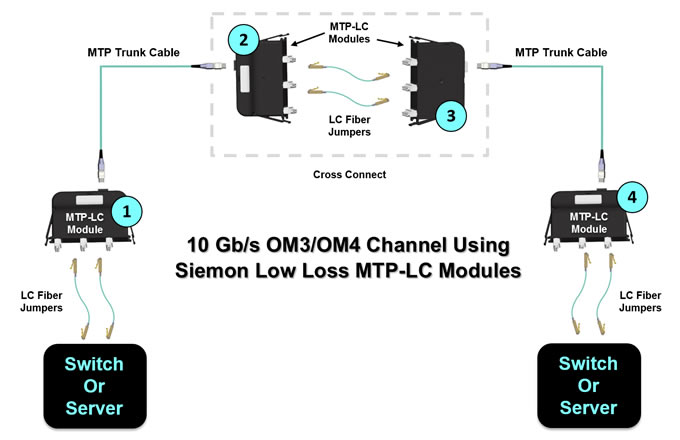
Figure 7. shows an OM3 40/100 GbE channel with six Fiberstore low loss MTP-MTP pass-through adapter plates and low loss trunks. This scenario offers 0.4 dB of headroom and provides even better manageability and security. All changes are made at the cross connects via MTP fiber jumpers, switches remain separate, and the MTP trunk cables need only be installed once.Once again, the cross connects can be located anywhere in the data center for maximum flexibility. This allows for one-time deployment of high fiber-count cabling from the cross connect at the interconnection switch to the cross connect at the access switch. Adding additional access switches can be accomplished with short fiber runs from the cross connect.
If the loss budget does not permit deploying six MTP to MTP adapters, one option is to deploy MTP to LC or MTP to MTP jumpers from the cross connect to the equipment, depending on the equipment interface. For example, if using OM4 fiber to extend the channel distance to 150 meters, up to five Low Loss MTP-MTP pass through adapters can be deployed.10 Gigabit Ethernet (10GbE) introduces a challenging 2.6-dB insertion loss limit on OM3 fiber cabling. This tight limit has led some industry observers to suggest it is not possible to meet the standard using regular, as opposed to low-loss, MTP cassette. Some have also suggested it is not possible to run fiber cabling the full 300-meter distance specified in the 10GBase-S standard when using MTP cassettes, whether those cassettes are standard or low-loss.
The TIA-568-C.0 standard allows for a maximum 2.6-dB insertion loss and 300-meter length with OM3 fiber cabling systems. While manufacturers frequently submit their copper cables for third-party testing to verify performance that meets or exceeds applicable standards, they typically have not had fiber cabling systems, including OM3, tested. This lack of independent verification can leave designers and operators of OM3 fiber networks uncertain what the true parameters are in designing premises applications.
For example, the maximum insertion loss for MTP-LC cassettes or modules as stated in the TIA specification is 1.5 dB. An unusually complicated–but not extreme–configuration might consist of four cassettes with a total of eight mated pairs. If each of these cassettes was at the headroom limit, then the insertion loss of 6.0 dB would exceed the allowable limit. Some vendors have addressed this possibility by offering low-loss cassettes. These cassettes typically come at a cost premium of approximately 50% over standard cassettes.
Posted by: kelonlau at
06:40 AM
| No Comments
| Add Comment
Post contains 968 words, total size 7 kb.
July 07, 2014
The most obvious benefit of the structured trunking system is the large reduction in the number of fiber optic cables under the raised floor. The smaller number of cables makes documenting what cables go where much easier. Better documentation means that tracing a fiber-optic link is much easier during problem determination and when planning for futrue growth.
A less apparent and often overlooked benefit of a structured system is its ability to make future data center growth implementation much easier. With a structured system installed, channels, and control unit I/O ports are connecte by MTP Trunk Cable to patch panels in the CPL. All the connetions between the equipment are made with short jumper cables between the patch panels in the CPL. When new equipment arrives. It is connected to patch pannels in the CPL also. Then, the actual reconfiguration takes place in the CPL by moving short jumper cables between the patch panels, not by moving long jumper cables under the raised floor.
The first FTS implementation solution is called modular panel-mount connectivity. This uses MPO TO MPO Cable to connect to the CPL.
The modular panel-mount boxes are designed so that you can changes the port type in the panel-mount box by unplugging the trunk and changing the modular inserts in the box.
Benefits:
* MTP-to-MTP trunks connect quickly to the panel-mount box.
* The connector type in front of the panel-mount can be easily changed.
* Panel mount capacity can be customized.
The second FTS implementation solution is called coupler plates connetivity. It uses MTP-LC duplex trunk cables to connect to the CPL.
The LC duplex small from factor optical connector is the standard for FTS connectivity, eliminating the need for multiple connector types at patch panels and for patch cables. By standardizing on a connector with a proven history of reliability, the different optical fiber connectors used in equipment do not create a management problem when a system configuration used in equipment do not create a management problem when a system configuration must change. The LC-duplex supports termination of both sizes of multimode fiber and single mode fiber. As a result, CPL patch panel connections and patch cables are easily mangaged and differentiated by their color. There are two key benefits:
* CPC port order at the panel mount is independent of the harness that plugs in at the CPC.
* Single connector type at the CPL
The MTP coupler brackets provide the mechanical support to connect the harness MTP connectors to the MPO Connector. They are directly mounted on CPC frames.
The maximum density of fiber trunk cables is 144 fiber, which use 12 Fiber MTP connectors on the CPC trunk cable end. The Trunk cables run under the raised floor and connect the harnesses in the CPC to the panel-mount box in the Central Patching Location.
Fiberstore manufactures and distributes a wide range of MTP MPO products including single mode or multimode MPO and MTP fiber cable, MPO Fiber Cassette and MTP Cassettes.High density MTP/MPO trunk cables with up to 288 fibers in a single cable. Fiberstore provides a very supportive customer service program for our clients when using our wide selection of products
Posted by: kelonlau at
07:27 AM
| No Comments
| Add Comment
Post contains 536 words, total size 4 kb.
July 04, 2014
Ribbon cables terminated with MPO connetors present some challenges when it comes to maintaining the correct signal crosssover in a segment consisting of multipe fiber optic srands. The ANSI/TIA-568-C.3 standard provies a set of "Guidelines for Maintaing Polarity Using Array Connetors" that decribe three types of MPO-to-MPO array cables, defined as Types A, B, and C. These cables are used to provide three different methods for maintaining a crossover connection. Method A is prefferred method, and is based on Type A MPO Fiber cables.
Figure 17-6 shows a Type A straight through ribbon cable with 12 fibers terminated in MPO connetor. A Method A backbone link is cabled "straight through", terminating in the cabling system patch panel. One end of the link will have a straight through patch cable, connetion from the patch panel to the Ethernet interface. The other end of the link will have a crossover cable connecting to the Ethernet interface. The guidelines recommend keeping all of the crossover patch cables at one end of the link, to keep the system as simple as possible and help the installer to avoid connecting the wrong type of patch cale.
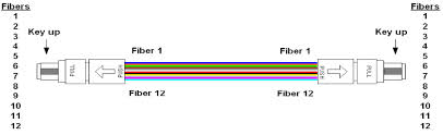
The guidelines also show Method B and Method C, which are two methods for providing a crossover patch built into the MPO backbone cables themselves. Given the complexity of these approaches and the difficulty of implementing them correctly, they are both rarely used.
As you can see, there are a variety of approaches to managing the signal crossover for the 12-fiber and 24-fiber systems needed to support 40 and 100 Gb/s Ethernet. For the best results, make sure you know which method your site is using in the cabling system, and order the correct MPO cable types to make the connections and achieve the signal crossover. Note that some vendors provide special MPO connectors that make it possible to change connector gender and polarity(crossover) in the field, which coulde be a handy way to resolve MPO-to-MPO connectivity issues.
To provide an introduction and basic information to readers, this section begins with a presentation of the components needed for a parallel optical MPO connection.
MPO connectors contact up to 24 fibers in a single connection. A connection must be stable and its ends correctly aligned. These aspects are essential for achieving the required transmission parameters. A defec-tive connection may even damage components and or cause the link to fail altogether.
MPO cables are delivered already terminated. This approach requires greater care in planning in advance but has a number of advantages: shorter installation times, tested and guaranteed quality and greater reli-ability.
Fiber trunk cables serve as a permanent link connecting the MPO modules to each other. Trunk cables are available with 12, 24, 48 and 72 fibers. Their ends are terminated with the customer's choice of 12-fiber or 24-fiber MPO connectors.

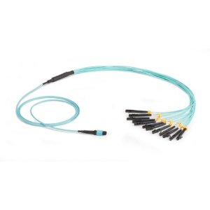
Harness cables provide a transition from multi-fiber cables to individual fibers or duplex connectors.The 12-fiber harness cables available from R&M are terminated with male or female connectors on the MPO side, the whips are available with LC or SC connectors.
Fiberstore supply MTP MPO fiber cables, MTP Cassette and MPO Cassette. MTP MPO cables are available in 4,8,12, 24, and 48 fiber array configurations. Many additional options and combinations are available. All fiber optic cables are customizable.
Posted by: kelonlau at
09:36 AM
| No Comments
| Add Comment
Post contains 557 words, total size 5 kb.
32 queries taking 0.1922 seconds, 74 records returned.
Powered by Minx 1.1.6c-pink.

