Fiber optic splitter, also named beam splitter, is based on a quartz substrate of integrated waveguide optical power distribution device, the same as coaxial cable transmission system, The optical network system also needs to be an optical signal coupled to the branch distribution, which requires thepassive optical splitter, Is one of the most important passive devices in the optical fiber link, is optical fiber tandem device with many input terminals and many output terminals, Especially applicable to a passive optical network (EPON, GPON, BPON, FTTX, FTTH etc.) to connect the MDF and the terminal equipment and to achieve the branching of the optical signal.
Fiber optic splitter is a key optical device in passive optical network (PON) systems, also known as a passive optical splitter, which splits the optical signal power evenly into all the output ports. In the PON field plant, a1x8 splitterto 1 × 32 splitter is placed on an electric pole, connecting the distribution optical cable in the air and the drop wire to the customer premises. A 1 × N splitter can be part of an N × N star coupler.
A fiber optic splitter is a device that splits the fiber optic light into several parts by a certain ratio. For example, when a beam of fiber optic light transmitted from a 1X4 equal ratio splitter, it will be divided into 4-fiber optic light by equal ratio that is each beam is 1/4 or 25% of the original source one. A fiber optic splitter is different from WDM. WDM can divide the different wavelength fiber optic light into different channels. fiber optic splitter divide the light power and send it to different channels.
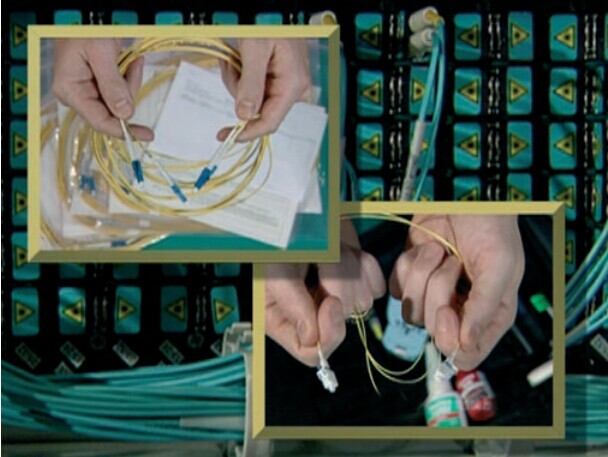
Most Splitters available in 900μm loose tube and 250μm bare fiber. 1x2 and 2x2 couplers come standard with a protective metal sleeve to cover the split. Higher output counts are built with a box to protect the splitting components
Fiberstore stocks hundreds of fiber optic adapter, fiber coupler, and fiber optic splitter solutions for both Multimode and Single mode fiber applications. We offer ST, SC, FC, LC, MTRJ, and MU style fiber optic adapters and fiber coupler products for just about every fiber cabling design requirement.
1
Touche. Great arguments. Keep up the great spirit.
Posted by: personal injury auto accident at June 25, 2015 01:22 AM (wlZo1)
2
I don't even know how I ended up here, but I thought this post was good.
I don't know who you are but certainly you are going to a famous blogger if
you are not already

Cheers!
Posted by: his comment is here at June 25, 2015 06:16 PM (ZEs4U)
3
Great blog right here! Additionally your site quite a bit up very fast!
What host are you the use of? Can I am getting your associate link for your host?
I wish my website loaded up as fast as yours lol
Posted by: kamagra tabletki na potencje at July 12, 2015 05:20 AM (Q9TRP)
4
Weed is demonstrated to have several medical uses which might be much better than most prescription medication.
Posted by: Lettie at July 13, 2015 08:38 AM (RSnuI)
5
The pricing for a hosting environment can be massively
different for different solutions and also the level of the company.
In general, you can expect to pay $ 50-10 per month, shared web hosting services.
This could pose both a physical and moral
problem for the owners of the children's website.
Don't forget that should you need more of 'whatever
they are offering' you can upgrade at a later stage; it
is a tad more difficult to downgrade. Finally the decision resides with you and your needs for
making the choice. If you wish to save some cash, shared hosting will be the best option for you.
With dedicated software, you can be assured that your website and server won't be attached by viruses and malware.
Going for a VPS hosting plan from the existing shared hosting plan. Dedicated servers ensure that no bandwidth, hard drive space, memory or anything else related to your website hosting
is shared with anyone else. Since there are not
many resources to create advanced websites with a free hosting service, it's best for personal sites, such as those for family or hobbies.
Posted by: Hostgator 1 Cent Coupon at July 13, 2015 10:41 AM (QPCwQ)
6
Whenever we look straight back during the organizations that
were taken to existence whenever you want over the last ten years, hardly any had a pre-defined Search Engine Optimization plan.
Posted by: Lance at July 13, 2015 12:16 PM (GndtI)
7
When you share a computer with several other websites you
are basically sharing the same system resources so if the machine only has 1 GB
of RAM if you install a script which uses
500 MB of RAM the other 50 sites which might be
sharing the same environment will be affected because your site is already consuming
half of the system resources. Unlike phone video conferencing more options for interaction between the presenter and the participants are available.
If you are planning to move from a shared to a dedicated hosting environment without having
to incur significant rise of costs, the logical step is to move to VPS hosting server first.
A fast approach to crop an image is to zoom in on the image how you would like
it cropped and take a screen shot of the zoomed in image.
Because of the scalable feature the required amount of space on these web hosting servers can be increased in accordance
with the requirements of the users. You have a place where you can test your web
projects, a place to store all the multimedia files that are played at network-enabled players in your home, and a separate machine to run a
torrent client. As technology progresses, so is the way how people makes transactions and
do business. However, the case is bit different with shared
hosting account. You as a user have multiple options in the market of cheap web
hosting to choose; you can settle for a greater tradeoff in addition to very cheap web
hosting service. Depending on the level of downloading you may chose a best web hosting server.
Posted by: Hostgator Coupon Code at July 13, 2015 12:24 PM (ghZoi)
8
Never rely on the application's built-in article builder and spinner (you
can use these for the tier 2 links, where quality is not an important factor).
Posted by: Magic Submitter Reviews at July 13, 2015 01:35 PM (ghZoi)
9
Pages designed to rank in serach engines for highly targeted search questions, typically designed to redirect searchers to
a typical page along with other ads.
Posted by: Celsa at July 13, 2015 02:48 PM (QPCwQ)
10
Particularly the CSS one, I'd no concept about this!!
Posted by: Claribel at July 13, 2015 03:17 PM (OFtUI)
11
Therefore, many thanks for sharing your knowledge!
Posted by: Etta at July 13, 2015 05:34 PM (cTHpi)
12
Proper underwriting of equipment becomes necessary.
Posted by: Mary at July 13, 2015 05:51 PM (virfp)
13
Relying upon your web application, the server can also require the following:
. Not to be brushed under the rug, there are also semi-dedicated and business hosting options, but those often still offer the same as a shared hosting plan, only with more space.
The host implements research team has been beneficial, economical and
beneficial to al the players in the industry today.
A fast approach to crop an image is to zoom in on the image how you would like it cropped and
take a screen shot of the zoomed in image. A dedicated hosting service, dedicated
server, or managed hosting service is a type of Internet hosting in which the client leases an entire server not shared with anyone
else. This has been brought about by the need to revolutionize and make
the internet experience one of the most entertaining and rewarding as possible.
For most of us who are trying to create and launch our own websites for the
first time, it can be a daunting task in many ways.
You enter an IP or DNS name and start and stop a port range, and this tool
will be a port scan shows all open ports. A server is a computing device
that manages the resources of a computer network.
Since there are not many resources to create advanced websites with a
free hosting service, it's best for personal sites, such as those for family or hobbies.
Posted by: Hostgator 1 Cent Coupon at July 13, 2015 06:36 PM (KZ722)
14
It is obvious that you need to check out the Website
requirements, then decide whether you require virtual private server hosting
or any other type of hosting service. Cutting-Edge Tools:
Certified Partners Get Exclusive Tools One of the major benefits of being a Microsoft Gold Partner is access to the latest Microsoft
tools and technologies. Market reports suggest that more than 90% of the
website hosted on the Internet do not receive great amount of traffic,
which implies that shared hosting can cater to the hosting needs of more than 90%
of the web owners out there in the online marketplace without creating a hole in their wallet.
Many of today's web hosts offer up affordable and reliable website hosting for only a few dollars a
month in some cases. While some of them are relatively simple and inexpensive, others
are of a greater complexity. Typically, shared hosting plans start at $5 - $20 per month.
For most of us who are trying to create and launch our own websites for the first time,
it can be a daunting task in many ways. Because of this, the demand
VPS hosting in India has increased considerably in the past
few years. Now website is more complex, contains CSS,
databases and scripting language. Small companies and individuals with small sites are probably better off with shared hosting.
Posted by: Hostgator Coupons July at July 14, 2015 12:01 AM (IMdx5)
15
Sweet blog! I found it while browsing on Yahoo News.
Do you have any suggestions on how to get listed in Yahoo News?
I've been trying for a while but I never seem to get there!
Cheers
Posted by: norsk spill at July 14, 2015 11:46 AM (oZwtu)
16
I was pretty pleased to uncover this page. I nee to to thank you for your time due to this fantastic read!!
I definitely liked every bit of itt aand I have you book marked to check out
neew information in your website.
Posted by: Acai-Beere Präparate at July 16, 2015 04:44 AM (LZ/xA)
17
The physical comfort of workers has a lot of influence on their
state of mind. Purchase these office items from suppliers that offer them
with low amounts of emission, since these levels do affect the quality of indoor air.
) There are also remnants from my sister's wedding presents,
from a time when giving mundane presents like pots and pans
was acceptable, along with an assortment of non-stick, easy
clean pans in various sizes.
Posted by: Shoes Cabinet at July 16, 2015 10:14 AM (nQY+c)
18
This is my first time visit at here and i am truly impressed to read all at single place.
Posted by: http://www.impera.mx at July 16, 2015 10:44 AM (8HIw+)
19
Hi to every body, it's my first pay a quick visit of this blog; this
blog includes remarkable and in fact good material for visitors.
Posted by: http://vai.la/ at July 16, 2015 11:20 AM (4KHTk)
20
He then buys 10 binary options from a binary choicss broker worth $one
hundred each just before the offered deadline.
Posted by: binary options strategy at July 16, 2015 05:20 PM (P2H7v)
21
wonderful video telling the truth, I did nnot require to acquire thhe
plan to know it is a scam, i use -flow ffor day-to-day revenue.
Posted by: binary options brokers us at July 16, 2015 07:21 PM (5rt1V)
22
Everything is very open with a clear clarification of the issues.
It was definitely informative. Yoour site is very helpful.
Thank you for sharing!
Posted by: http://eshops.primeapps.gr/component/k2/author/39935 at July 16, 2015 07:47 PM (gnedq)
23
Through the use of this website, you agree to the Terms of Use and Privateness Coverage Wikipedia® is a registered trademark of the Wikimedia Basis, Inc.
Posted by: ted 2 cały film at July 17, 2015 03:13 AM (SsCsX)
24
It's an awesome paragraph for all the online people;
they will get advanntage from it I am sure.
Posted by: 1Blitzbrigadehack1.Wordpress.Com at July 17, 2015 11:32 AM (zdnge)
25
My spouse and I stumbled over here different web page and thought I may as well
check things out. I like what I see so now i am following you.
Look forward to finding out about your web page repeatedly.
Posted by: tips for travelling to europe at July 17, 2015 11:54 AM (uAK8Q)
26
Place the alarms in areas frequented by workers, such as offices, break rooms,
hallways, appliance rooms and other work areas. I also emphasized on one
of its benefit concerning indoor heat reduction of your home.
In older properties there have ben countless cases of tenants actually removing the batteries from detectors because
of annoying warning beeps when the battery is wearing out.
Posted by: alarm Hua Hin at July 17, 2015 02:05 PM (XNwX+)
27
Modern vehicles are complex machines which are engineered and mass produced
for the purpose intended, as designed. Then, you will need to drill some holes, and install some brackets.
It is critical that you home contain a home alarm and monitoring system.
Posted by: alarm Hua Hin at July 17, 2015 06:14 PM (XNwX+)
28
Skoro wiem, że woli kalsze w gwiazdki od tych
w kwiaty, to mogę ama szybko je kupić po pracy.
Posted by: Lindsey at July 18, 2015 10:15 AM (TBQq5)
29
Hurrah, that's what I was looking for, what a stuff! existing here at this web site, thanks admin of this website.
Posted by: ac repair st louis mo at July 18, 2015 12:04 PM (zDJOf)
30
I've been surfing online more than three hours today,
yet I never found any interesting article like yours.
It's pretty worth enough for me. In my opinion, if all web owners and
bloggers made good content as you did, the net will be much more useful than ever before.|
I could not resist commenting. Perfectly written!|
I'll immediately grasp your rss as I can not find your
email subscription hyperlink or e-newsletter service.
Do you have any? Kindly allow me know so that I may subscribe.
Thanks.|
It's perfect time to make some plans for the future and it's time to be happy.
I've read this post and if I could I wish to suggest you few interesting things or tips.
Perhaps you can write next articles referring to this article.
I want to read more things about it!|
It's appropriate time to make some plans for the longer term and it
is time to be happy. I've learn this post and if I may I want to counsel
you some fascinating issues or suggestions. Maybe you could write next articles
referring to this article. I want to learn more issues approximately it!|
I have been surfing on-line greater than 3 hours
as of late, but I never found any fascinating article like yours.
It is pretty worth sufficient for me. In my opinion, if all website owners and bloggers made excellent content as you did, the net will be a lot more helpful than ever before.|
Ahaa, its good discussion on the topic of this post
here at this web site, I have read all that, so
now me also commenting here.|
I am sure this article has touched all the internet users, its really really pleasant article on building up new weblog.|
Wow, this post is nice, my younger sister is analyzing these kinds of things, so I am
going to inform her.|
bookmarked!!, I love your blog!|
Way cool! Some extremely valid points! I appreciate you penning
this write-up plus the rest of the website is also really good.|
Hi, I do believe this is a great blog. I stumbledupon it
I'm
going to come back once again since I book marked it. Money and
freedom is the best way to change, may you be rich and continue to help
others.|
Woah! I'm really enjoying the template/theme of this blog.
It's simple, yet effective. A lot of times it's challenging to get that "perfect balance" between usability and visual appearance.
I must say you've done a fantastic job with this. Also,
the blog loads very fast for me on Safari. Exceptional Blog!|
These are truly wonderful ideas in regarding blogging.
You have touched some good things here. Any way keep up wrinting.|
I enjoy what you guys are usually up too. Such
clever work and exposure! Keep up the excellent works guys I've included you guys to my personal blogroll.|
Hey! Someone in my Myspace group shared this site with us so I came
to give it a look. I'm definitely enjoying the information. I'm
book-marking and will be tweeting this to my followers! Terrific blog and great design.|
I like what you guys are usually up too. This type of clever work and
coverage! Keep up the amazing works guys I've included you guys to my personal blogroll.|
Hi there would you mind sharing which blog platform you're working with?
I'm looking to start my own blog soon but I'm having a difficult time making a decision between BlogEngine/Wordpress/B2evolution and Drupal.
The reason I ask is because your design seems different then most blogs and I'm looking for something completely unique.
P.S Apologies for being off-topic but I had to ask!|
Hi would you mind letting me know which webhost
you're using? I've loaded your blog in 3 different internet browsers and
I must say this blog loads a lot faster then most.
Can you recommend a good web hosting provider at a
reasonable price? Many thanks, I appreciate it!|
Everyone loves it whenever people get together and share thoughts.
Great blog, stick with it!|
Thank you for the good writeup. It in fact was a amusement account it.
Look advanced to far added agreeable from you!
However, how could we communicate?|
Hey there just wanted to give you a quick heads up. The words in your content seem
to be running off the screen in Safari. I'm not sure if this is a formatting issue or something to do with browser compatibility but I thought I'd post to let
you know. The layout look great though! Hope you get the problem fixed soon. Kudos|
This is a topic which is near to my heart... Many thanks!
Exactly where are your contact details though?|
It's very effortless to find out any matter on net as compared to textbooks, as I found this article
at this web page.|
Does your blog have a contact page? I'm having problems locating it but, I'd like
to send you an email. I've got some ideas for your blog you might be interested
in hearing. Either way, great blog and I look forward to seeing it expand over time.|
Hello! I've been following your blog for a while now and finally got the courage
to go ahead and give you a shout out from Atascocita Tx!
Just wanted to mention keep up the excellent
work!|
Greetings from Los angeles! I'm bored to death at work so I decided
to check out your website on my iphone during
lunch break. I enjoy the information you present here and can't wait
to take a look when I get home. I'm shocked at how quick your
blog loaded on my mobile .. I'm not even using WIFI, just 3G ..
Anyways, superb site!|
Its like you read my thoughts! You appear to understand so much about this, like you wrote the guide
in it or something. I believe that you just could do with some p.c.
to power the message home a bit, however instead of that, this is great blog.
A fantastic read. I will certainly be back.|
I visited various web sites except the audio quality for audio songs current at this
web page is in fact wonderful.|
Hi, i read your blog from time to time and i own a similar one and i
was just wondering if you get a lot of spam
remarks? If so how do you prevent it, any plugin or anything you can advise?
I get so much lately it's driving me crazy so any assistance is very much appreciated.|
Greetings! Very helpful advice in this particular
post! It's the little changes that make the most important changes.
Many thanks for sharing!|
I seriously love your blog.. Great colors & theme.
Did you create this amazing site yourself? Please reply
back as I'm planning to create my own blog and would love to find out where you got this from or just what the theme is called.
Cheers!|
Hello there! This article couldn't be written any better!
Looking through this post reminds me of my previous roommate!
He continually kept preaching about this. I'll forward this post to
him. Fairly certain he'll have a great read. Thanks for sharing!|
Amazing! This blog looks exactly like my old one! It's on a entirely different topic but it has
pretty much the same page layout and design. Excellent choice of colors!|
There is certainly a lot to learn about this topic.
I really like all of the points you made.|
You've made some decent points there. I looked on the web to learn more about the issue and found most individuals will go along with your views on this web site.|
What's up, I log on to your blogs daily. Your humoristic
style is witty, keep doing what you're doing!|
I simply could not leave your website before suggesting that I really enjoyed the standard info an individual supply for your guests?
Is going to be again ceaselessly to check out
new posts|
I need to to thank you for this good read!!
I definitely loved every bit of it. I have got you book-marked to look
at new things you post…|
Hi, just wanted to tell you, I liked this article. It was helpful.
Keep on posting!|
Hello, I enjoy reading through your article post. I wanted to
write a little comment to support you.|
I every time spent my half an hour to read this blog's articles all the time along with a cup of coffee.|
I all the time emailed this website post page to all my associates, for the reason that
if like to read it then my links will too.|
My developer is trying to persuade me to move to .net from PHP.
I have always disliked the idea because of the costs.
But he's tryiong none the less. I've been using WordPress on a number of
websites for about a year and am worried about switching to another platform.
I have heard good things about blogengine.net.
Is there a way I can import all my wordpress content into it?
Any kind of help would be greatly appreciated!|
Hi! I could have sworn I've been to this website before but after looking at many of the posts I realized it's new to me.
Regardless, I'm certainly delighted I stumbled upon it and I'll be book-marking
it and checking back regularly!|
Terrific work! This is the type of information that are supposed to be shared across the web.
Shame on Google for not positioning this put up higher!
Come on over and visit my site . Thanks =)|
Heya i'm for the first time here. I found this board and I find It really useful
& it helped me out much. I hope to give something back
and help others like you helped me.|
Hi, I do believe your site might be having browser compatibility problems.
Whenever I take a look at your website in Safari, it looks fine however when opening in IE, it has
some overlapping issues. I simply wanted to provide you
with a quick heads up! Aside from that, wonderful blog!|
Somebody essentially help to make significantly articles I would state.
This is the first time I frequented your website page and to
this point? I surprised with the analysis you made to create this particular put up extraordinary.
Fantastic job!|
Heya i'm for the primary time here. I found this board and I find It really helpful & it
helped me out much. I'm hoping to present something
back and aid others such as you helped me.|
Hello there! I simply want to offer you a big thumbs up for the great info you have got right here on this post.
I will be returning to your web site for more soon.|
I all the time used to study piece of writing in news papers but now as I am a user of web therefore from now
I am using net for content, thanks to web.|
Your mode of explaining the whole thing in this post is genuinely good,
all can effortlessly know it, Thanks a lot.|
Hello there, I discovered your site by means of Google even as searching for a similar
subject, your web site came up, it appears great.
I've bookmarked it in my google bookmarks.
Hello there, simply become aware of your weblog through Google, and found that it's truly informative.
I'm gonna watch out for brussels. I will be grateful in case you continue this in future.
A lot of other folks might be benefited out of your writing.
Cheers!|
I'm curious to find out what blog system you are using? I'm having some
minor security problems with my latest website and I'd like to find something more risk-free.
Do you have any recommendations?|
I'm really impressed with your writing skills as well
as with the layout on your weblog. Is this a paid theme or did you modify it yourself?
Anyway keep up the nice quality writing, it
is rare to see a great blog like this one nowadays.|
I am extremely impressed along with your writing skills and also with the structure for your
weblog. Is this a paid topic or did you modify it yourself?
Anyway keep up the excellent high quality writing, it is rare
to peer a great blog like this one nowadays..|
Hello, Neat post. There is a problem along with your web site in web explorer, could test this?
IE nonetheless is the marketplace chief and a large element
of people will leave out your great writing because of this problem.|
I am not sure where you're getting your information, but great topic.
I needs to spend some time learning more or understanding more.
Thanks for great information I was looking for this info for my mission.|
Hello, i think that i saw you visited my site
so i came to “return the favorâ€.I am attempting to find things
to enhance my web site!I suppose its ok to use a few of your ide\
Posted by: louis vuitton bags uk at July 18, 2015 12:25 PM (O/xQ3)
31
Greetings from Ohio! I'm bored to tears at work so I decided to browse your website on my iphone during lunch break.
I really like the info you present here and can't wait to take
a look when I get home. I'm amazed at how fast your blog loaded on my phone ..
I'm not even using WIFI, just 3G .. Anyways,
good blog!
Posted by: Diabetes Destroyer Review at July 19, 2015 05:37 PM (O6nzQ)
32
As you see, no matter whether marketplace costs are going up or down, there is
propfit to be produced with binaryy possibilities trading.
Posted by: binary options robot at July 20, 2015 03:42 PM (kwbt/)
33
Please let me know if you're looking for a writer for your weblog.
You have some really great posts and I believe I would be
a good asset. If you ever want to take some of the load off, I'd love to write some content for your blog in exchange for a link back to mine.
Please blast me an email if interested. Many thanks!
Posted by: Online Success Plan System at July 21, 2015 06:55 PM (a4f/C)
34
{
{I have|I've} been {surfing|browsing} online more than {three|3|2|4} hours today, yet I never found
any interesting article like yours. {It's|It is} pretty worth enough for me.
{In my opinion|Personally|In my view}, if all {webmasters|site
owners|website owners|web owners} and bloggers
made good content as you did, the {internet|net|web} will be {much more|a lot more} useful than ever before.|
I {couldn't|could not} {resist|refrain from} commenting.
{Very well|Perfectly|Well|Exceptionally well} written!|
{I will|I'll} {right away|immediately} {take hold of|grab|clutch|grasp|seize|snatch} your {rss|rss feed} as I {can not|can't} {in finding|find|to find} your {email|e-mail} subscription {link|hyperlink}
or {newsletter|e-newsletter} service. Do {you have|you've} any?
{Please|Kindly} {allow|permit|let} me {realize|recognize|understand|recognise|know}
{so that|in order that} I {may just|may|could} subscribe.
Thanks.|
{It is|It's} {appropriate|perfect|the best} time to make some plans for the future and
{it is|it's} time to be happy. {I have|I've} read this post
and if I could I {want to|wish to|desire to} suggest
you {few|some} interesting things or {advice|suggestions|tips}.
{Perhaps|Maybe} you {could|can} write next articles referring to this article.
I {want to|wish to|desire to} read {more|even more} things about
it!|
{It is|It's} {appropriate|perfect|the best} time to make {a few|some} plans for {the future|the longer term|the long run} and {it is|it's} time to be happy.
{I have|I've} {read|learn} this {post|submit|publish|put up} and if I
{may just|may|could} I {want to|wish to|desire to}
{suggest|recommend|counsel} you {few|some} {interesting|fascinating|attention-grabbing} {things|issues} or {advice|suggestions|tips}.
{Perhaps|Maybe} you {could|can} write {next|subsequent} articles {relating to|referring to|regarding} this article.
I {want to|wish to|desire to} {read|learn} {more|even more}
{things|issues} {approximately|about} it!|
{I have|I've} been {surfing|browsing} {online|on-line} {more than|greater than} {three|3}
hours {these days|nowadays|today|lately|as of late}, {yet|but} I {never|by no means} {found|discovered}
any {interesting|fascinating|attention-grabbing} article like
yours. {It's|It is} {lovely|pretty|beautiful}
{worth|value|price} {enough|sufficient} for me. {In my opinion|Personally|In my view}, if all {webmasters|site owners|website owners|web owners} and
bloggers made {just right|good|excellent} {content|content material} as {you did|you probably did}, the {internet|net|web} {will be|shall be|might be|will probably be|can be|will likely be} {much more|a
lot more} {useful|helpful} than ever before.|
Ahaa, its {nice|pleasant|good|fastidious} {discussion|conversation|dialogue} {regarding|concerning|about|on the topic of} this {article|post|piece of writing|paragraph} {here|at
this place} at this {blog|weblog|webpage|website|web site},
I have read all that, so {now|at this time} me also commenting {here|at this place}.|
I am sure this {article|post|piece of writing|paragraph} has touched all the internet {users|people|viewers|visitors}, its really really {nice|pleasant|good|fastidious}
{article|post|piece of writing|paragraph} on building up new {blog|weblog|webpage|website|web site}.|
Wow, this {article|post|piece of writing|paragraph} is {nice|pleasant|good|fastidious},
my {sister|younger sister} is analyzing {such|these|these kinds of} things, {so|thus|therefore}
I am going to {tell|inform|let know|convey} her.|
{Saved as a favorite|bookmarked!!}, {I really like|I like|I love} {your blog|your site|your web site|your website}!|
Way cool! Some {very|extremely} valid points! I appreciate you {writing this|penning this} {article|post|write-up} {and the|and
also the|plus the} rest of the {site is|website is} {also very|extremely|very|also really|really} good.|
Hi, {I do believe|I do think} {this is an excellent|this is
a great} {blog|website|web site|site}. I stumbledupon it
{I will|I am
going to|I'm going to|I may} {come back|return|revisit} {once again|yet again} {since I|since i have} {bookmarked|book marked|book-marked|saved as a favorite} it.
Money and freedom {is the best|is the greatest} way to change, may you be rich and continue to {help|guide} {other
people|others}.|
Woah! I'm really {loving|enjoying|digging} the template/theme of this {site|website|blog}.
It's simple, yet effective. A lot of times it's {very hard|very
difficult|challenging|tough|difficult|hard} to get that "perfect balance" between {superb usability|user friendliness|usability} and {visual appearance|visual appeal|appearance}.
I must say {that you've|you have|you've} done a {awesome|amazing|very good|superb|fantastic|excellent|great} job with
this. {In addition|Additionally|Also}, the blog loads {very|extremely|super} {fast|quick} for me on {Safari|Internet explorer|Chrome|Opera|Firefox}.
{Superb|Exceptional|Outstanding|Excellent} Blog!|
These are {really|actually|in fact|truly|genuinely} {great|enormous|impressive|wonderful|fantastic} ideas
in {regarding|concerning|about|on the topic of} blogging.
You have touched some {nice|pleasant|good|fastidious} {points|factors|things} here.
Any way keep up wrinting.|
{I love|I really like|I enjoy|I like|Everyone loves} what you guys {are|are usually|tend to be} up too.
{This sort of|This type of|Such|This kind of} clever work and {exposure|coverage|reporting}!
Keep up the {superb|terrific|very good|great|good|awesome|fantastic|excellent|amazing|wonderful} works guys I've {incorporated||added|included} you guys to {|my|our||my
personal|my own} blogroll.|
{Howdy|Hi there|Hey there|Hi|Hello|Hey}! Someone in my {Myspace|Facebook} group shared this
{site|website} with us so I came to {give it a look|look it
over|take a look|check it out}. I'm definitely {enjoying|loving} the information. I'm {book-marking|bookmarking} and will be tweeting
this to my followers! {Terrific|Wonderful|Great|Fantastic|Outstanding|Exceptional|Superb|Excellent} blog and {wonderful|terrific|brilliant|amazing|great|excellent|fantastic|outstanding|superb}
{style and design|design and style|design}.|
{I love|I really like|I enjoy|I like|Everyone loves} what you guys {are|are usually|tend to be} up
too. {This sort of|This type of|Such|This kind of} clever work and {exposure|coverage|reporting}!
Keep up the {superb|terrific|very good|great|good|awesome|fantastic|excellent|amazing|wonderful} works guys I've {incorporated|added|included} you guys to {|my|our|my
personal|my own} blogroll.|
{Howdy|Hi there|Hey there|Hi|Hello|Hey} would you mind {stating|sharing} which blog platform you're {working with|using}?
I'm {looking|planning|going} to start my own blog {in the near
future|soon} but I'm having a {tough|difficult|hard} time {making a decision|selecting|choosing|deciding} between BlogEngine/Wordpress/B2evolution and Drupal.
The reason I ask is because your {design and style|design|layout} seems different
then most blogs and I'm looking for something {completely unique|unique}.
P.S {My apologies|Apologies|Sorry} for {getting|being} off-topic but I
had to ask!|
{Howdy|Hi there|Hi|Hey there|Hello|Hey} would you mind letting me know which {webhost|hosting company|web host} you're {utilizing|working with|using}?
I've loaded your blog in 3 {completely different|different} {internet browsers|web browsers|browsers} and I must
say this blog loads a lot {quicker|faster} then most. Can you {suggest|recommend} a good {internet hosting|web hosting|hosting} provider at a {honest|reasonable|fair} price?
{Thanks a lot|Kudos|Cheers|Thank you|Many thanks|Thanks}, I appreciate
it!|
{I love|I really like|I like|Everyone loves} it {when people|when individuals|when folks|whenever people} {come together|get together} and share {opinions|thoughts|views|ideas}.
Great {blog|website|site}, {keep it up|continue the good work|stick with it}!|
Thank you for the {auspicious|good} writeup. It in fact was
a amusement account it. Look advanced to {far|more} added agreeable from you!
{By the way|However}, how {can|could} we communicate?|
{Howdy|Hi there|Hey there|Hello|Hey} just wanted to give you a
quick heads up. The {text|words} in your {content|post|article} seem
to be running off the screen in {Ie|Internet explorer|Chrome|Firefox|Safari|Opera}.
I'm not sure if this is a {format|formatting} issue or something to do with
{web browser|internet browser|browser} compatibility but
I {thought|figured} I'd post to let you know. The {style and design|design and
style|layout|design} look great though! Hope you get the {problem|issue} {solved|resolved|fixed}
soon. {Kudos|Cheers|Many thanks|Thanks}|
This is a topic {that is|that's|which is} {close to|near to} my heart...
{Cheers|Many thanks|Best wishes|Take care|Thank you}!
{Where|Exactly where} are your contact details
though?|
It's very {easy|simple|trouble-free|straightforward|effortless} to find out any {topic|matter} on {net|web} as compared to {books|textbooks}, as I found this {article|post|piece of writing|paragraph} at this {website|web site|site|web
page}.|
Does your {site|website|blog} have a contact page?
I'm having {a tough time|problems|trouble} locating
it but, I'd like to {send|shoot} you an {e-mail|email}.
I've got some {creative ideas|recommendations|suggestions|ideas}
for your blog you might be interested in hearing. Either way, great {site|website|blog} and I look forward to seeing it {develop|improve|expand|grow}
over time.|
{Hola|Hey there|Hi|Hello|Greetings}! I've been {following|reading}
your {site|web site|website|weblog|blog} for {a long time|a while|some time} now and finally got the {bravery|courage} to go
ahead and give you a shout out from {New Caney|Kingwood|Huffman|Porter|Houston|Dallas|Austin|Lubbock|Humble|Atascocita} {Tx|Texas}!
Just wanted to {tell you|mention|say} keep up the {fantastic|excellent|great|good} {job|work}!|
Greetings from {Idaho|Carolina|Ohio|Colorado|Florida|Los angeles|California}!
I'm {bored to tears|bored to death|bored} at work so I decided to {check out|browse} your {site|website|blog} on my iphone during lunch
break. I {enjoy|really like|love} the {knowledge|info|information} you {present|provide} here and
can't wait to take a look when I get home. I'm {shocked|amazed|surprised} at
how {quick|fast} your blog loaded on my {mobile|cell phone|phone} ..
I'm not even using WIFI, just 3G .. {Anyhow|Anyways}, {awesome|amazing|very good|superb|good|wonderful|fantastic|excellent|great} {site|blog}!|
Its {like you|such as you} {read|learn} my {mind|thoughts}!
You {seem|appear} {to understand|to know|to
grasp} {so much|a lot} {approximately|about} this,
{like you|such as you} wrote the {book|e-book|guide|ebook|e book} in it or something.
{I think|I feel|I believe} {that you|that you simply|that you just} {could|can} do with {some|a few} {%|p.c.|percent} to {force|pressure|drive|power} the message {house|home} {a
bit|a little bit}, {however|but} {other than|instead of} that, {this is|that is} {great|wonderful|fantastic|magnificent|excellent}
blog. {A great|An excellent|A fantastic} read.
{I'll|I will} {definitely|certainly} be back.|
I visited {multiple|many|several|various} {websites|sites|web sites|web
pages|blogs} {but|except|however} the audio {quality|feature} for audio songs {current|present|existing} at this {website|web site|site|web page} is {really|actually|in fact|truly|genuinely} {marvelous|wonderful|excellent|fabulous|superb}.|
{Howdy|Hi there|Hi|Hello}, i read your blog {occasionally|from time to time} and i own a
similar one and i was just {wondering|curious} if you get a lot of spam {comments|responses|feedback|remarks}?
If so how do you {prevent|reduce|stop|protect against} it, any
plugin or anything you can {advise|suggest|recommend}?
I get so much lately it's driving me {mad|insane|crazy}
so any {assistance|help|support} is very much appreciated.|
Greetings! {Very helpful|Very useful} advice {within this|in this particular} {article|post}!
{It is the|It's the} little changes {that make|which will make|that produce|that will make}
{the biggest|the largest|the greatest|the most important|the most significant} changes.
{Thanks a lot|Thanks|Many thanks} for sharing!|
{I really|I truly|I seriously|I absolutely} love {your blog|your site|your website}..
{Very nice|Excellent|Pleasant|Great} colors & theme.
Did you {create|develop|make|build} {this website|this site|this web site|this
amazing site} yourself? Please reply back as I'm {looking
to|trying to|planning to|wanting to|hoping to|attempting to} create {my own|my
very own|my own personal} {blog|website|site} and
{would like to|want to|would love to} {know|learn|find
out} where you got this from or {what the|exactly
what the|just what the} theme {is called|is named}.
{Thanks|Many thanks|Thank you|Cheers|Appreciate it|Kudos}!|
{Hi there|Hello there|Howdy}! This {post|article|blog post} {couldn't|could not} be written {any better|much better}!
{Reading through|Looking at|Going through|Looking through} this {post|article}
reminds me of my previous roommate! He {always|constantly|continually} kept {talking about|preaching about} this.
{I will|I'll|I am going to|I most certainly will} {forward|send} {this article|this information|this post} to him.
{Pretty sure|Fairly certain} {he will|he'll|he's
going to} {have a good|have a very good|have a great} read.
{Thank you for|Thanks for|Many thanks for|I appreciate you for} sharing!|
{Wow|Whoa|Incredible|Amazing}! This blog looks {exactly|just} like my old one!
It's on a {completely|entirely|totally} different {topic|subject} but it has pretty much the same {layout|page layout} and
design. {Excellent|Wonderful|Great|Outstanding|Superb} choice
of colors!|
{There is|There's} {definately|certainly} {a lot to|a great deal to} {know about|learn about|find out
about} this {subject|topic|issue}. {I like|I love|I really like} {all the|all of the} points {you made|you've made|you
have made}.|
{You made|You've made|You have made} some {decent|good|really good} points there.
I {looked|checked} {on the internet|on the web|on the net} {for more info|for more
information|to find out more|to learn more|for additional information} about the issue and found {most individuals|most people} will go along
with your views on {this website|this site|this web site}.|
{Hi|Hello|Hi there|What's up}, I {log on to|check|read} your {new stuff|blogs|blog} {regularly|like every week|daily|on a regular basis}.
Your {story-telling|writing|humoristic} style is {awesome|witty}, keep {doing what you're
doing|up the good work|it up}!|
I {simply|just} {could not|couldn't} {leave|depart|go away} your {site|web
site|website} {prior to|before} suggesting that I {really|extremely|actually} {enjoyed|loved}
{the standard|the usual} {information|info} {a person|an individual} {supply|provide} {for your|on your|in your|to your} {visitors|guests}?
Is {going to|gonna} be {back|again} {frequently|regularly|incessantly|steadily|ceaselessly|often|continuously} {in order to|to} {check up on|check out|inspect|investigate cross-check}
new posts|
{I wanted|I needed|I want to|I need to} to thank you for this {great|excellent|fantastic|wonderful|good|very good} read!!
I {definitely|certainly|absolutely} {enjoyed|loved}
every {little bit of|bit of} it. {I have|I've got|I have got} you {bookmarked|book marked|book-marked|saved as a favorite} {to check out|to look at} new {stuff you|things you} post…|
{Hi|Hello|Hi there|What's up}, just wanted to {mention|say|tell you}, I {enjoyed|liked|loved} this {article|post|blog post}.
It was {inspiring|funny|practical|helpful}. Keep on posting!|
{Hi there|Hello}, I enjoy reading {all of|through} your {article|post|article post}.
I {like|wanted} to write a little comment to support you.|
I {always|constantly|every time} spent my half an hour to read this {blog|weblog|webpage|website|web site}'s {articles|posts|articles or reviews|content} {everyday|daily|every day|all the time} along with a {cup|mug} of coffee.|
I {always|for all time|all the time|constantly|every time} emailed this {blog|weblog|webpage|website|web
site} post page to all my {friends|associates|contacts}, {because|since|as|for the reason that} if like to read it {then|after that|next|afterward} my {friends|links|contacts} will too.|
My {coder|programmer|developer} is trying to {persuade|convince} me to move to .net from PHP.
I have always disliked the idea because of the {expenses|costs}.
But he's tryiong none the less. I've been using {Movable-type|WordPress} on {a
number of|a variety of|numerous|several|various} websites for about a year and am {nervous|anxious|worried|concerned} about switching to another platform.
I have heard {fantastic|very good|excellent|great|good} things about blogengine.net.
Is there a way I can {transfer|import} all my wordpress
{content|posts} into it? {Any kind of|Any} help would be {really|greatly} appreciated!|
{Hello|Hi|Hello there|Hi there|Howdy|Good day}! I could have sworn I've {been to|visited} {this blog|this web
site|this website|this site|your blog} before but after {browsing through|going through|looking at} {some of the|a few of the|many of the} {posts|articles} I realized it's
new to me. {Anyways|Anyhow|Nonetheless|Regardless}, I'm {definitely|certainly}
{happy|pleased|delighted} {I found|I discovered|I came across|I stumbled upon} it and I'll be {bookmarking|book-marking} it and checking back {frequently|regularly|often}!|
{Terrific|Great|Wonderful} {article|work}! {This is|That
is} {the type of|the kind of} {information|info} {that are meant to|that are supposed to|that should}
be shared {around the|across the} {web|internet|net}. {Disgrace|Shame}
on {the {seek|search} engines|Google} for {now not|not|no longer} positioning this {post|submit|publish|put up} {upper|higher}!
Come on over and {talk over with|discuss with|seek advice from|visit|consult with} my {site|web site|website} .
{Thank you|Thanks} =)|
Heya {i'm|i am} for the first time here. I {came across|found}
this board and I find It {truly|really} useful
& it helped me out {a lot|much}. I hope to give something
back and {help|aid} others like you {helped|aided} me.|
{Hi|Hello|Hi there|Hello there|Howdy|Greetings}, {I think|I believe|I
do believe|I do think|There's no doubt that} {your site|your website|your web site|your
blog} {might be|may be|could be|could possibly be} having {browser|internet browser|web browser} compatibility {issues|problems}.
{When I|Whenever I} {look at your|take a look at your} {website|web site|site|blog} in Safari, it looks fine {but when|however when|however, if|however, when} opening in {Internet Explorer|IE|I.E.}, {it
has|it's got} some overlapping issues. {I just|I simply|I merely} wanted
to {give you a|provide you with a} quick heads up!
{Other than that|Apart from that|Besides that|Aside from
that}, {fantastic|wonderful|great|excellent} {blog|website|site}!|
{A person|Someone|Somebody} {necessarily|essentially} {lend a hand|help|assist} to make
{seriously|critically|significantly|severely} {articles|posts} {I would|I might|I'd} state.
{This is|That is} the {first|very first} time I frequented your {web page|website
page} and {to this point|so far|thus far|up to now}?
I {amazed|surprised} with the {research|analysis} you made to {create|make} {this actual|this particular} {post|submit|publish|put up} {incredible|amazing|extraordinary}.
{Great|Wonderful|Fantastic|Magnificent|Excellent} {task|process|activity|job}!|
Heya {i'm|i am} for {the primary|the first} time here. I {came across|found} this board and I
{in finding|find|to find} It {truly|really} {useful|helpful} & it helped me out {a lot|much}.
{I am hoping|I hope|I'm hoping} {to give|to offer|to
provide|to present} {something|one thing} {back|again} and
{help|aid} others {like you|such as you} {helped|aided} me.|
{Hello|Hi|Hello there|Hi there|Howdy|Good day|Hey there}!
{I just|I simply} {would like to|want to|wish to} {give you a|offer you
a} {huge|big} thumbs up {for the|for your} {great|excellent} {info|information} {you
have|you've got|you have got} {here|right here} on this post.
{I will be|I'll be|I am} {coming back to|returning to} {your
blog|your site|your website|your web site} for more soon.|
I {always|all the time|every time} used to {read|study}
{article|post|piece of writing|paragraph} in news papers but now as I am
a user of {internet|web|net} {so|thus|therefore} from now I am using net for {articles|posts|articles or reviews|content},
thanks to web.|
Your {way|method|means|mode} of {describing|explaining|telling}
{everything|all|the whole thing} in this {article|post|piece of writing|paragraph} is {really|actually|in fact|truly|genuinely}
{nice|pleasant|good|fastidious}, {all|every one} {can|be able to|be capable of} {easily|without difficulty|effortlessly|simply} {understand|know|be aware of} it, Thanks
a lot.|
{Hi|Hello} there, {I found|I discovered} your {blog|website|web site|site} {by means of|via|by the use
of|by way of} Google {at the same time as|whilst|even as|while} {searching for|looking for} a {similar|comparable|related} {topic|matter|subject}, your {site|web site|website} {got here|came} up, it {looks|appears|seems|seems to be|appears to be
like} {good|great}. {I have|I've} bookmarked it in my google bookmarks.
{Hello|Hi} there, {simply|just} {turned into|became|was|become|changed
into} {aware of|alert to} your {blog|weblog} {thru|through|via} Google,
{and found|and located} that {it is|it's} {really|truly} informative.
{I'm|I am} {gonna|going to} {watch out|be careful} for brussels.
{I will|I'll} {appreciate|be grateful} {if you|should you|when you|in the event you|in case you|for those who|if you happen to} {continue|proceed} this {in future}.
{A lot of|Lots of|Many|Numerous} {other folks|folks|other people|people}
{will be|shall be|might be|will probably be|can be|will likely be} benefited
{from your|out of your} writing. Cheers!|
{I am|I'm} curious to find out what blog {system|platform} {you have been|you happen to be|you are|you're} {working with|utilizing|using}?
I'm {experiencing|having} some {minor|small} security {problems|issues} with my latest {site|website|blog} and {I would|I'd} like
to find something more {safe|risk-free|safeguarded|secure}.
Do you have any {solutions|suggestions|recommendations}?|
{I am|I'm} {extremely|really} impressed with your writing skills {and also|as well as}
with the layout on your {blog|weblog}. Is this a paid theme or
did you {customize|modify} it yourself? {Either way|Anyway} keep up the
{nice|excellent} quality writing, {it's|it is} rare to see a {nice|great} blog like this one {these days|nowadays|today}.|
{I am|I'm} {extremely|really} {inspired|impressed} {with your|together with your|along with
your} writing {talents|skills|abilities} {and also|as {smartly|well|neatly} as} with
the {layout|format|structure} {for your|on your|in your|to your}
{blog|weblog}. {Is this|Is that this} a paid {subject|topic|subject
matter|theme} or did you {customize|modify} it {yourself|your self}?
{Either way|Anyway} {stay|keep} up the {nice|excellent}
{quality|high quality} writing, {it's|it is} {rare|uncommon} {to peer|to see|to look} a {nice|great} {blog|weblog} like
this one {these days|nowadays|today}..|
{Hi|Hello}, Neat post. {There is|There's} {a problem|an issue} {with your|together
with your|along with your} {site|web site|website} in {internet|web} explorer, {may|might|could|would} {check|test} this?
IE {still|nonetheless} is the {marketplace|market} {leader|chief} and {a large|a good|a big|a huge} {part of|section of|component to|portion of|component of|element of} {other
folks|folks|other people|people} will {leave out|omit|miss|pass over} your
{great|wonderful|fantastic|magnificent|excellent} writing {due to|because of} this problem.|
{I'm|I am} not sure where {you are|you're} getting your
{info|information}, but {good|great} topic. I needs to spend some time learning {more|much more} or understanding more.
Thanks for {great|wonderful|fantastic|magnificent|excellent} {information|info} I was looking for this {information|info} for my mission.|
{Hi|Hello}, i think that i saw you visited my {blog|weblog|website|web
site|site} {so|thus} i came to “return the favorâ€.{I am|I'm} {trying to|attempting to} find things to {improve|enhance} my
{website|site|web site}!I suppose its ok to use {some of|a few of} your
ideas!!
\
Posted by: customized bobble head at July 22, 2015 09:47 AM (A1nsC)
35
For newest news you have to visit web and on the web I found
this website as a most excellent web site for latest updates.
Posted by: cheap fake ray bans at July 23, 2015 11:39 AM (jrXLt)
36
craigslist phone verified accounts on sale :
$4 per account contact to buy - Yahoo Messenger - anjudevianju skype - anjudevi
www.freshPVA.com Instant Delivery.
Also we are undertaking re-verification of craigslist phone verified accountse been surfing online more than three hours these
days, but I by no means found any fascinating article like yours.
It's beautiful value sufficient for me. In my view, if all webmasters and bloggers made
just right content material as you did, the internet might be much more helpful than ever before.|
Ahaa, its pleasant discussion about this piece of writing here at this website,
I have read all that, so now me also commenting at this place.|
I am sure this paragraph has touched all the internet people,
its really really nice article on building up new website.|
Wow, this post is good, my younger sister is analyzing these things, so I am going to let know her.|
Saved as a favorite, I like your website!|
Way cool! Some very valid points! I appreciate you penning this write-up plus the rest of the site is also very good.|
Hi, I do think this is an excellent site. I stumbledupon it
I'm going to return
yet again since I book-marked it. Money and freedom is the best way to
change, may you be rich and continue to help others.|
Woah! I'm really digging the template/theme
of this site. It's simple, yet effective. A lot of times it's very hard to get that "perfect balance" between usability and appearance.
I must say you have done a very good job with this.
Additionally, the blog loads extremely fast for me on Internet explorer.
Exceptional Blog!|
These are actually fantastic ideas in regarding blogging. You have
touched some nice points here. Any way keep up wrinting.|
I really like what you guys tend to be up too. This type of clever work and reporting!
Keep up the wonderful works guys I've you guys to my personal blogroll.|
Howdy! Someone in my Myspace group shared this website with us so
I came to check it out. I'm definitely loving the information.
I'm book-marking and will be tweeting this to my followers!
Fantastic blog and wonderful design.|
I really like what you guys are usually up too. This kind of clever work and reporting!
Keep up the great works guys I've incorporated you guys to my own blogroll.|
Hey there would you mind sharing which blog platform you're working with?
I'm going to start my own blog in the near future but I'm having a difficult time choosing between BlogEngine/Wordpress/B2evolution and
Drupal. The reason I ask is because your design and style seems different then most blogs and I'm looking for something completely unique.
P.S Apologies for being off-topic but I had to ask!|
Hey would you mind letting me know which webhost you're using?
I've loaded your blog in 3 completely different browsers and I
must say this blog loads a lot faster then most. Can you suggest a good web hosting
provider at a honest price? Kudos, I appreciate it!|
I like it when folks get together and share opinions. Great blog, keep it up!|
Thank you for the good writeup. It in fact was a amusement account it.
Look advanced to more added agreeable from you! By the way, how could we communicate?|
Howdy just wanted to give you a quick heads up. The text in your article seem to
be running off the screen in Firefox. I'm not sure if this is
a format issue or something to do with browser compatibility but I
figured I'd post to let you know. The style and design look great though!
Hope you get the problem resolved soon. Thanks|
This is a topic which is close to my heart... Take care!
Exactly where are your contact details though?|
It's very trouble-free to find out any matter on net as
compared to books, as I found this post at this web site.|
Does your blog have a contact page? I'm having trouble locating it but, I'd like
to send you an email. I've got some ideas for your blog you might be interested in hearing.
Either way, great website and I look forward to seeing it grow over
time.|
Hi! I've been following your site for a long time now and finally got the courage to go ahead and give you a
shout out from Houston Texas! Just wanted to tell you keep up the great work!|
Greetings from Carolina! I'm bored to death at work
so I decided to browse your blog on my iphone during lunch break.
I really like the information you provide here and can't wait to take a look when I get home.
I'm amazed at how fast your blog loaded on my phone .. I'm not even using
WIFI, just 3G .. Anyways, amazing site!|
Its like you learn my thoughts! You seem to grasp a lot approximately this, like
you wrote the guide in it or something. I believe that you simply could do with a few percent to power the
message home a bit, however instead of that, that is fantastic blog.
An excellent read. I'll certainly be back.|
I visited various blogs except the audio quality for audio songs current
at this website is really marvelous.|
Howdy, i read your blog from time to time and i own a similar one and i was just curious
if you get a lot of spam remarks? If so how do you reduce it, any
plugin or anything you can advise? I get so much lately it's driving me insane so any help is very much appreciated.|
Greetings! Very helpful advice in this particular post!
It is the little changes that produce the biggest changes.
Many thanks for sharing!|
I really love your blog.. Great colors & theme. Did you develop this website
yourself? Please reply back as I'm planning to create my own site and want to know where you got this from or exactly
what the theme is named. Many thanks!|
Hi there! This post could not be written
any better! Reading through this post reminds me of my previous roommate!
He continually kept preaching about this. I most certainly will forward this information to him.
Fairly certain he will have a great read. Thanks for sharing!|
Incredible! This blog looks just like my old one! It's on a
completely different subject but it has pretty much the same page layout and design.
Great choice of colors!|
There's definately a great deal to learn about this topic.
I really like all the points you have made.|
You have made some decent points there. I checked on the internet to learn more about the issue and
found most individuals will go along with your views on this web site.|
What's up, I read your new stuff on a regular basis. Your story-telling style is witty,
keep up the good work!|
I just couldn't go away your site prior to suggesting that
I really enjoyed the standard information a person provide on your visitors?
Is gonna be back continuously in order to check out new
posts|
I needed to thank you for this fantastic read!! I absolutely enjoyed every bit of it.
I've got you bookmarked to look at new things you post…|
What's up, just wanted to tell you, I loved this blog post.
It was helpful. Keep on posting!|
I drop a comment each time I appreciate a post on a blog or I have something to valuable to contribute to the
discussion. Usually it is caused by the fire communicated in the
post I looked at. And on this post Fiber optic cable.
I was excited enough to drop a comment
I actually do have some questions
for you if it's okay. Could it be only me or does it look like like some of the comments appear like coming
from brain dead folks? :-P And, if you are writing at additional online social sites, I would like to follow you.
Could you list all of all your communal sites like your Facebook page, twitter feed, or linkedin profile?|
Hi there, I enjoy reading all of your article.
I wanted to write a little comment to support
you.|
I every time spent my half an hour to read this web site's
posts every day along with a cup of coffee.|
I for all time emailed this weblog post page to all my friends, since if like to read it next my links will too.|
My coder is trying to persuade me to move to .net from PHP.
I have always disliked the idea because of the costs. But he's tryiong none the less.
I've been using WordPress on several websites for about
a year and am anxious about switching to another platform.
I have heard great things about blogengine.net. Is there a way I
can transfer all my wordpress posts into it?
Any help would be really appreciated!|
Hello there! I could have sworn I've visited this
web site before but after going through many of the articles
I realized it's new to me. Regardless, I'm certainly happy
I came across it and I'll be bookmarking it and checking back regularly!|
Great article! That is the kind of information that are meant to be
shared across the internet. Shame on Google for no longer positioning this post upper!
Come on over and visit my web site . Thanks =)|
Heya i am for the first time here. I came across this board and I find It really useful &
it helped me out a lot. I hope to give something back and aid others like you
aided me.|
Hi, I do think your web site may be having web browser compatibility issues.
When I look at your blog in Safari, it looks fine however,
when opening in IE, it's got some overlapping issues. I simply wanted
to provide you with a quick heads up! Aside from that, great blog!|
Someone essentially help to make critically posts I
would state. This is the first time I frequented your website page and so far?
I amazed with the analysis you made to make this actual submit incredible.
Wonderful process!|
Heya i am for the primary time here. I found this board and I in finding It really useful & it helped me out
a lot. I am hoping to offer something again and aid others such as you helped me.|
Hi! I simply would like to give you a big thumbs up for your excellent information you have right here on this post.
I will be returning to your web site for more soon.|
I all the time used to read paragraph in news papers but now as
I am a user of web so from now I am using net for articles or reviews, thanks to web.|
Your method of telling the whole thing in this post is really
fastidious, all can without difficulty be aware of it,
Thanks a lot.|
Hi there, I found your web site via Google whilst searching for a comparable
topic, your web site came up, it seems great. I've bookmarked it in my google
bookmarks.
Hi there, just was alert to your weblog thru Google, and found that
it's truly informative. I am gonna be careful for brussels.
I will appreciate if you happen to proceed this in future.
Many people will be benefited from your writing.
Cheers!|
I am curious to find out what blog system you're utilizing?
I'm having some small security issues with my latest blog and I would like to
find something more secure. Do you have any solutions?|
I'm really impressed with your writing skills and also with the layout on your weblog.
Is this a paid theme or did you customize it yourself? Either way keep
up the excellent quality writing, it's rare to see a
nice blog like this one today.|
I'm extremely impressed together with your writing abilities
and also with the structure to your weblog. Is that this a paid subject matter or did you modify it
yourself? Either way keep up the excellent high quality writing, it is uncommon to peer a great weblog like this
one these days..|
Hello, Neat post. There is an issue along
with your site in internet explorer, would check this?
IE still is the marketplace leader and a big component of other folks will pass over your excellent writing due
to this problem.|
I am not sure where you're getting your info, but good topic.
I needs to spend some time learning much more or understanding
more. Thanks for great information I was looking for this information for my
mission.|
Hello, i think that i saw you visited my weblog so i came
to “return the favorâ€.I'm trying to find things to enhance my website!I suppose its ok to use a few of your
ideas!!|
Hi, i feel that i saw you visited my site thus i came to go back the choose?.I
am trying to to find issues to improve my site!I assume its ok to
use a few of your ideas!!|
Hi there, just became alert to your blog through Google, and found that it's really informative.
I'm gonna watch out for brussels. I will be grateful if you continue
this in future. Lots of people will be benefited from your
writing. Cheers!|
I am now not sure the place you're getting your
information, but great topic. I must spend some time finding out more or understanding more.
Thanks for magnificent information I used to be on the lookout for this info for my mission.|
Hello my family member! I wish to say that this article is amazing, great
written and include approximately all vital infos.
I'd like to peer extra posts like this .|
hello!,I like your writing so a lot! proportion we keep up
a correspondence extra approximately your post on AOL?
I require an expert in this space to solve my problem.
May be that is you! Looking ahead to look you. |
I'm really loving the theme/design of your weblog.
Do you ever run into any browser compatibility issues? A few
of my blog readers have complained about my site not
operating correctly in Explorer but looks great in Opera.
Do you have any suggestions to help fix this issue?|
Great info. Lucky me I discovered your site by chance (stumbleupon).
I have book marked it for later!|
It's impressive that you are getting thoughts from this article as well as from our argument made at this time.|
If you wish for to improve your knowledge simply keep visiting this web site and be
updated with the hottest news update posted
here.|
What's Taking place i'm new to this, I stumbled upon this
I've discovered It positively helpful and it has helped me out loads.
I am hoping to contribute & assist other users like its helped me.
Great job.|
Hurrah, that's what I was searching for, what a stuff!
existing here at this webpage, thanks admin of this web page.|
If you want to obtain a good deal from this post then you have to apply these
techniques to your won webpage.|
It's an awesome article designed for all the internet
visitors; they will take advantage from it I am sure.|
I have learn several excellent stuff here. Certainly price bookmarking for revisiting.
I surprise how a lot attempt you place to create this type of
excellent informative website.|
This is a very good tip especially to those fresh to
the blogosphere. Brief but very precise information… Many thanks for sharing this one.
A must read post!|
I've been exploring for a little for any high-quality articles or
blog posts in this kind of house . Exploring in Yahoo I eventually stumbled upon this site.
Studying this info So i'm glad to convey that I have a very good uncanny feeling I found out
exactly what I needed. I so much undoubtedly will
make certain to don?t forget this website and give it a glance on a constant basis.|
Having read this I believed it was very enlightening. I
appreciate you taking the time and effort to put this informative article together.
I once again find myself personally spending a significant
amount of time both reading and commenting.
But so what, it was still worthwhile!|
Quality content is the key to be a focus for the viewers to pay a quick visit the site, that's what this
site is providing.|
Link exchange is nothing else however it is simply placing the other person's weblog link
on your page at suitable place and other person
will also do same for you.|
I have read so many articles concerning the blogger lovers
but this paragraph is in fact a pleasant article,
keep it up.|
Really when someone doesn't understand afterward its up to
other people that they will help, so here it happens.|
You can definitely see your enthusiasm in the work you write.
The arena hopes for more passionate writers such as
you who are not afraid to mention how they believe.
Always follow your heart.|
Excellent post. I'm going through many of these issues as well..|
Excellent web site you have here.. It's hard to find high-quality writing like yours nowadays.
I honestly appreciate individuals like you!
Take care!!|
I was recommended this website by my cousin. I'm not sure
whether this post is written by him as no one else know such detailed about my problem.
You are amazing! Thanks!|
Good article! We are linking to this particularly great post on our
website. Keep up the great writing.|
Oh my goodness! Amazing article dude! Thank you, However I am going through issues with your RSS.
I don't understand the reason why I am unable to join
it. Is there anyone else getting similar RSS issues?
Anybody who knows the answer can you kindly respond?
Thanks!!|
Amazing blog! Do you have any tips and hints for aspiring writers?
I'm hoping to start my own site soon but I'm a little lost on everything.
Would you suggest starting with a free platform like Wordpress or go for a paid option?
There are so many choices out there that I'm totally confused ..
Any tips? Kudos!|
It's difficult to find knowledgeable people about this subject,
however, you sound like you know what you're talking about!
Thanks|
I don't even know the way I stopped up here, but I believed this
put up was once good. I don't recognise who you might
be but definitely you're going to a well-known blogger if you
are not already. Cheers!|
Fastidious respond in return of this matter with genuine arguments and telling everything regarding that.|
I don't even know how I ended up here, but I thought this post was great.
I do not know who you are but certainly you're going to a famous blogger if
you aren't already
Cheers!|
We are a gaggle of volunteers and starting a brand new scheme in our community.
Your site offered us with valuable info to work on.
You've performed an impressive activity and our entire neighborhood will probably be grateful to you.|
Fine way of describing, and nice piece of writing to obtain facts regarding my presentation focus, which
i am going to deliver in academy.|
Great blog right here! Also your web site a lot up very
fast! What web host are you the usage of? Can I get your affiliate
hyperlink to your host? I wish my website loaded up as fast as yours lol|
I love your blog.. very nice colors & theme.
Did you design this website yourself or did you hire someone to do it for you?
Plz reply as I'm looking to construct my own blog and would like to know where u got this from.
thanks a lot|
We're a group of volunteers and starting a new scheme in our community.
Your web site provided us with valuable info to work on. You
have done an impressive job and our whole community will be grateful to
you.|
Appreciate this post. Will try it out.|
Asking questions are truly good thing if you are
not understanding anything fully, but this piece of
writing presents good understanding even.|
Have you ever considered about including a little
bit more than just your articles? I mean, what you say is important
and everything. However think of if you added some great visuals or video clips to give your posts more, "pop"!
Your content is excellent but with pics and videos, this website could undeniably be one of the best in its niche.
Great blog!|
Your style is unique compared to other people I've read stuff from.
I appreciate you for posting when you have the opportunity, Guess I will just bookmark this page.|
Very nice post. I simply stumbled upon your blog and wished to mention that I have really
enjoyed surfing around your blog posts. After all I will be subscribing
in your rss feed and I am hoping you write once more soon!|
I'm impressed, I must say. Seldom do I come across a blog that's both
equally educative and engaging, and without a doubt, you've hit the nail on the head.
The issue is something that not enough folks are speaking intelligently about.
I'm very happy that I found this in my search for something relating
to this.|
Hmm it seems like your blog ate my first comment (it was extremely long) so I guess I'll just sum
it up what I wrote and say, I'm thoroughly enjoying your blog.
I too am an aspiring blog writer but I'm still new to everything.
Do you have any points for inexperienced blog writers?
I'd really appreciate it.|
Very nice post. I just stumbled upon your weblog and wished to say that I have really enjoyed browsing your
blog posts. After all I will be subscribing to your feed and I hope
you write again very soon!|
I like the helpful information you provide in your articles.
I'll bookmark your weblog and check again here frequently.
I am quite sure I will learn a lot of new stuff right here!
Good luck for the next!|
If you are going for most excellent contents like I do, simply pay a
quick visit this web site everyday since it presents feature contents,
thanks|
Write more, thats all I have to say. Literally, it seems as though you relied
on the video to make your point. You definitely know what youre talking about,
why waste your intelligence on just posting videos to your blog
when you could be giving us something enlightening to read?|
Highly descriptive post, I enjoyed that bit.
Will there be a part 2?|
Excellent post. I used to be checking constantly this weblog and I am impressed!
Extremely useful info specifically the last phase :
) I maintain such information much. I was looking for this particular information for a very lengthy time.
Thanks and best of luck. |
Nice post. I was checking constantly this blog and I'm impressed!
Very useful information particularly the last part :
) I care for such info much. I was looking for this certain information
for a very long time. Thank you and best of luck.|
Great post.|
After looking over a handful of the blog articles on your blog, I truly appreciate
your technique of blogging. I book marked it to my bookmark site list and will be checking back in the
near future. Take a look at my website too and tell me your opinion.|
A motivating discussion is worth comment. I believe that you ought to publish more about this issue,
it might not be a taboo matter but typically folks don't talk about such issues.
To the next! Kind regards!!|
certainly like your web site however you need to take a look at
the spelling on quite a few of your posts. Many of them are rife with spelling problems and I to find it
very troublesome to tell the truth then again I will surely come
again again.|
I do agree with all of the ideas you have offered in your post.
They're really convincing and can definitely work.
Nonetheless, the posts are very quick for starters. May just you please extend them a little from subsequent time?
Thanks for the post.|
We stumbled over here from a different page and thought I might check things out.
I like what I see so now i am following you. Look forward to exploring your web page for a second time.|
Very good blog post. I definitely love this site. Keep it up!|
Have you ever considered creating an ebook or guest authoring
on other sites? I have a blog based upon on the same topics you discuss and would love to have you share some stories/information.
I know my visitors would appreciate your work. If
you're even remotely interested, feel free to shoot me an e-mail.|
My partner and I stumbled over here from a different website and thought I should check things out.
I like what I see so now i'm following you. Look
forward to finding out about your web page for a
second time.|
Nice blog here! Also your site loads up fast! What web host are you using?
Can I get your affiliate link to your host? I wish my web site loaded up as quickly as yours lol|
Hey there! I know this is kind of off topic but I was wondering which
blog platform are you using for this site? I'm getting
sick and tired of Wordpress because I've had issues with hackers
and I'm looking at alternatives for another platform.
I would be fantastic if you could point me in the direction of
a good platform.|
Hello! I know this is kind of off topic but I was wondering
if you knew where I could get a captcha plugin for my comment form?
I'm using the same blog platform as yours and I'm having difficulty finding one?
Thanks a lot!|
Hey! This is my first visit to your blog! We are a
team of volunteers and starting a new project in a community in the
same niche. Your blog provided us useful information to work on.
You have done a outstanding job!|
After I initially left a comment I seem to have clicked
the -Notify me when new comments are added- checkbox and now every time a comment is added I receive
four emails with the same comment. Perhaps there is a way you can remove me from that service?
Thanks a lot!|
First of all I want to say excellent blog! I had a quick question
which I'd like to ask if you don't mind. I was curious to find out how you center yourself and clear your
mind before writing. I've had trouble clearing my
mind in getting my thoughts out. I truly do enjoy writing but it
just seems like the first 10 to 15 minutes are wasted simply just trying to figure out how to begin.
Any ideas or tips? Appreciate it!|
This site was... how do you say it? Relevant!! Finally I've found something which helped me.
Appreciate it!|
Everything is very open with a precise clarification of the issues.
It was definitely informative. Your website is very useful.
Many thanks for sharing!|
This design is wicked! You certainly know how to keep a reader entertained.
Between your wit and your videos, I was almost moved to
start my own blog (well, almost...HaHa!) Excellent job.
I really enjoyed what you had to say, and more than that, how you presented it.
Too cool!|
It's going to be finish of mine day, but before end I am reading this enormous article to improve my experience.|
I go to see day-to-day some web sites and sites to read content, however this blog offers feature based
posts.|
Heya! I just wanted to ask if you ever have any trouble with hackers?
My last blog (wordpress) was hacked and I ended up losing months of hard work due to no data backup.
Do you have any solutions to protect against hackers?|
I think the admin of this web page is truly working
hard in support of his website, as here every data is quality based
data.|
At this time I am ready to do my breakfast, later than having my breakfast coming again to read additional news.|
I just like the helpful info you supply to your articles.
I'll bookmark your weblog and test once more right here regularly.
I'm rather sure I'll be informed lots of new stuff right right
here! Good luck for the following!|
I think this is one of the most important info for me. And
i'm glad reading your article. But should remark on few general things,
The site style is ideal, the articles is really great : D.
Good job, cheers|
It's a shame you don't have a donate button! I'd definitely donate to this excellent
blog! I suppose for now i'll settle for bookmarking and
adding your RSS feed to my Google account.
I look forward to fresh updates and will share this website with my Facebook group.
Chat soon!|
I’m not that much of a internet reader to be honest but your blogs really nice, keep it up!
I'll go ahead and bookmark your website to come back in the future.
Many thanks|
This paragraph is actually a good one it helps new web viewers,
who are wishing in favor of blogging.|
It's actually a nice and useful piece of information.
I am satisfied that you shared this useful info with
us. Please stay us informed like this. Thank you
for sharing.|
This post gives clear idea for the new users of
blogging, that truly how to do blogging.|
Howdy! Quick question that's completely off topic.
Do you know how to make your site mobile friendly?
My website looks weird when browsing from my iphone 4.
I'm trying to find a theme or plugin that might be able to resolve this problem.
If you have any recommendations, please share. Appreciate it!|
It is not my first time to go to see this website, i am browsing this
website dailly and get pleasant information from here daily.|
Interesting blog! Is your theme custom made or did you download it from somewhere?
A design like yours with a few simple tweeks would really make my blog stand out.
Please let me know where you got your design. Appreciate it|
This paragraph will assist the internet users for creating new webpage or even
a weblog from start to end.|
I know this if off topic but I'm looking into starting my own blog and was curious what all is needed to get set up?
I'm assuming having a blog like yours would cost a
pretty penny? I'm not very web savvy so I'm not 100% sure.
Any tips or advice would be greatly appreciated. Thanks|
My family every time say that I am killing my time here at
net, however I know I am getting know-how everyday by reading thes good articles or reviews.|
Spot on with this write-up, I actually believe this site needs a lot more attention.
I'll probably be returning to see more, thanks for the information!|
I know this website presents quality dependent posts and extra material,
is there any other site which presents these kinds of things in quality?|
I read this piece of writing completely regarding the
difference of latest and earlier technologies, it's remarkable
article.|
I feel that is one of the most vital information for me.
And i am glad reading your article. But should observation
on some basic things, The web site style is ideal, the
articles is actually excellent : D. Just right job, cheers|
I really like reading through a post that can make men and women think.
Also, many thanks for permitting me to comment!|
Thanks very nice blog!|
Every weekend i used to visit this web site, as i want enjoyment, since
this this web page conations genuinely fastidious funny data too.|
I do not know if it's just me or if perhaps everybody else experiencing
issues with your site. It seems like some of the written
text on your posts are running off the screen. Can somebody else please provide feedback and
let me know if this is happening to them too?
This might be a problem with my internet browser
because I've had this happen before. Cheers|
You really make it seem so easy with your presentation but I find this topic to be
actually something which I think I would never understand.
It seems too complex and extremely broad for me. I am looking forward for your next post, I'll try
to get the hang of it!|
I would like to thank you for the efforts you've put in penning
this site. I really hope to check out the same high-grade content from you in
the future as well. In fact, your creative writing abilities has
motivated me to get my own website now
|
It's actually very complicated in this full of activity life to listen news on TV, thus I
only use world wide web for that reason, and get the latest news.|
I am genuinely grateful to the owner of this web page
who has shared this great article at at this place.|
I am regular visitor, how are you everybody?
This article posted at this website is truly good.|
It's really a cool and useful piece of information. I am glad that you simply shared this useful info with us.
Please keep us informed like this. Thank you for sharing.|
Yes! Finally something about phone verification.|
Definitely imagine that that you said. Your favorite
justification appeared to be at the web the simplest factor to take into accout of.
I say to you, I definitely get irked while people think about worries that they just
do not recognize about. You managed to hit the nail upon the top and defined out the entire thing with
no need side effect , folks could take a signal. Will likely
be again to get more. Thank you|
Definitely believe that which you stated. Your favorite justification appeared to be on the net the simplest thing to be aware of.
I say to you, I definitely get annoyed while people
think about worries that they just don't know about.
You managed to hit the nail upon the top and defined out the whole thing without having side effect , people can take a signal.
Will probably be back to get more. Thanks|
I am in fact glad to glance at this blog posts which contains lots of helpful facts, thanks
for providing such information.|
You actually make it appear really easy along with your presentation however I in finding this matter to be
actually one thing which I think I'd never understand.
It seems too complicated and extremely broad for me.
I am looking ahead on your subsequent publish, I'll try to get the
grasp of it!|
Incredible points. Great arguments. Keep up the amazing work.|
I'm really enjoying the design and layout of your site.
It's a very easy on the eyes which makes it much more pleasant for me to come here and
visit more often. Did you hire out a developer to create your theme?
Exceptional work!|
Stunning quest there. What happened after? Thanks!|
all the time i used to read smaller posts that as well clear their motive, and
that is also happening with this paragraph which I am reading at this time.|
You need to take part in a contest for one of the best
blogs on the net. I most certainly will recommend this blog!|
I'm excited to find this great site. I need to to thank you for ones time due
to this fantastic read!! I definitely liked every little bit of it
and i also have you saved as a favorite to look at new things
on your site.|
Wonderful blog! I found it while surfing around on Yahoo News.
Do you have any tips on how to get listed in Yahoo News?
I've been trying for a while but I never seem to get there!
Thank you|
Wonderful website. Plenty of useful information
here. I am sending it to several friends ans also sharing
in delicious. And naturally, thank you in your effort!|
excellent submit, very informative. I'm wondering why the opposite experts of
this sector don't realize this. You should proceed your writing.
I am confident, you have a great readers' base already!|
Fantastic beat ! I would like to apprentice while you amend your website,
how could i subscribe for a blog web site? The account aided me a acceptable deal.
I had been tiny bit acquainted of this your broadcast offered bright clear
idea|
wonderful issues altogether, you just won a logo new reader.
What may you recommend in regards to your put
up that you made a few days ago? Any certain?|
Do you mind if I quote a couple of your posts as long as I provide credit and
sources back to your blog? My blog is in the exact same area of interest as yours and my visitors would really benefit from a lot of the information you provide here.
Please let me know if this ok with you. Thank you!|
With havin so much content do you ever run into any problems of
plagorism or copyright infringement? My blog has a lot of unique content
I've either written myself or outsourced but it looks like
a lot of it is popping it up all over the
internet without my agreement. Do you know any ways
to help prevent content from being stolen? I'd definitely appreciate it.|
Wonderful goods from you, man. I've take note your stuff prior
to and you're just too fantastic. I actually like what you've bought right here, really like what you're
stating and the way in which wherein you say it. You make it entertaining and you still
care for to keep it smart. I can't wait to read far more from you.
That is really a great website.|
If some one wishes to be updated with hottest technologies after that he must
be pay a visit this website and be up to date daily.|
I was wondering if you ever thought of changing the
layout of your website? Its very well written; I
love what youve got to say. But maybe you could
a little more in the way of content so people could connect with it better.
Youve got an awful lot of text for only having 1 or
two images. Maybe you could space it out better?|
Very rapidly this site will be famous amid all blog viewers, due
to it's good posts|
If some one wants expert view concerning running a blog afterward i advise
him/her to pay a quick visit this weblog, Keep up the fastidious work.|
Excellent goods from you, man. I've understand your stuff previous to and you're just extremely wonderful.
I actually like what you've acquired here, certainly like what
you're stating and the way in which you say it.
You make it enjoyable and you still care for to keep it sensible.
I can not wait to read far more from you. This is actually a great site.|
Excellent beat ! I wish to apprentice while
you amend your site, how could i subscribe for a
blog website? The account aided me a acceptable deal.
I were a little bit acquainted of this your broadcast provided bright transparent concept|
Usually I don't learn article on blogs, however I would
like to say that this write-up very pressured me to check out and do
it! Your writing style has been surprised me. Thanks, very
great article.|
I was recommended this web site through my cousin.
I'm no longer certain whether or not this post is written by him as nobody else realize such exact
about my problem. You are incredible! Thanks!|
Hey There. I found your blog using msn. This is a very well written article.
I will make sure to bookmark it and come back to read more of your useful info.
Thanks for the post. I will certainly comeback.|
Hello There. I found your blog the use of msn.
This is a really smartly written article. I'll be sure to
bookmark it and come back to learn extra of your helpful info.
Thanks for the post. I will definitely return.|
Thanks for one's marvelous posting! I quite enjoyed reading it, you can be a great author.
I will be sure to bookmark your blog and will come back at some point.
I want to encourage you to definitely continue your great writing, have a nice morning!|
Hey there! I could have sworn I've been
to this blog before but after checking through some of the
post I realized it's new to me. Anyways, I'm definitely
delighted I found it and I'll be book-marking and checking back
frequently!|
Thanks for sharing such a fastidious thinking,
piece of writing is pleasant, thats why i have read it fully|
hey there and thank you for your info – I've certainly
picked up something new from right here. I did however expertise a few technical issues using this
web site, since I experienced to reload the web site a lot
of times previous to I could get it to load correctly. I had
been wondering if your hosting is OK? Not that I am complaining, but sluggish loading instances times
will very frequently affect your placement in google and can damage your high-quality score if advertising and marketing with Adwords.
Well I am adding this RSS to my email and can look out for
a lot more of your respective interesting content.
Make sure you update this again very soon.|
What i do not understood is actually how you
are now not really much more well-appreciated than you may
be right now. You're very intelligent. You know therefore considerably in terms of this matter, produced me in my opinion believe it from so many various angles.
Its like men and women aren't involved except it's one thing to
do with Girl gaga! Your personal stuffs nice. All the time handle it up!|
Wow! Finally I got a webpage from where I be able to genuinely obtain useful facts concerning my study and knowledge.|
When someone writes an piece of writing he/she keeps the thought of a user in his/her brain that how
a user can know it. Therefore that's why this piece of writing is great.
Thanks!|
You're so awesome! I do not believe I've truly read a single thing like this
before. So wonderful to discover someone with a few original thoughts on this topic.
Seriously.. thanks for starting this up. This web site is something that is needed on the internet, someone with some originality!|
Thanks for one's marvelous posting! I seriously enjoyed reading it, you could be a great author.I will be sure to bookmark your blog and will eventually come back down the road.
I want to encourage you to ultimately continue your great
job, have a nice evening!|
Appreciation to my father who told me regarding this
webpage, this weblog is really awesome.|
Post writing is also a excitement, if you be acquainted with after
that you can write or else it is complicated to write.|
No matter if some one searches for his necessary thing, thus
he/she wants to be available that in detail, thus that thing is maintained over here.|
Thanks for finally talking about >Fiber optic cable
Posted by: phone verified accounts at July 25, 2015 04:42 PM (16Sen)
37
VerÒ¯ Ç¥ood Ôrite-up. I absolutely appreciate thÑ–s site.
Τhanks!
Posted by: Helene at July 26, 2015 11:45 PM (/MGp7)
38
nike free runs ukHis unwillingness to conform led to famous clashes with former coach Larry Brown, who guided Iverson and the 76ers to
the NBA Finals in 2001. nike free run 2 review
black nike free run 2Think about it. If you look at
your customers with dollar signs and take a hard sell approach with them, you are increasing the likelyhood of customers having
a poor experience with you, and they now have tools (Twitter, Facebook, etc.)
at their disposal to tell the world about it. This can be extremely damaging to your brand and image..
nike free run black and white
Posted by: nike free runs uk at July 27, 2015 09:22 AM (dyTbG)
39
ralph lauren outlet online australiaLet's face it: Saturday Night Live hasn't been funny
since the mid 90s. polo ralph lauren factory store
ralph lauren dog clothesWith online training, you
would get your weekly practice schedule that you need to follow in letter and spirit.
The online coach would want you to fill the weekly shot chart so that you could analyze your strength and also find your weakness.
The weekly chart would help you improve your game and also it would show whether you are improving
or not.. ralph lauren cheap online
Posted by: ralph lauren outlet online australia at July 27, 2015 09:27 AM (dyTbG)
40
Attractive section of content. I just stumbled upon your site and in accession capital to say
that I acquire in fact loved account your blog posts. Any way I will be
subscribing for your feeds or even I success you access constantly fast.
Posted by: judi bola terpercaya at July 29, 2015 10:45 AM (F7/I6)
41
Hi, I desire to subscribe for this weblog to take most recent updates, therefore
where can i do it please help out.
Posted by: apex t reviews at July 30, 2015 10:45 AM (mbkD7)
42
This post provides clear idea for the new viewers of blogging, that in fact how to do blogging.
Posted by: bibit kroto at July 30, 2015 11:22 PM (DTgHn)
43
You ought to be a part of a contest for one of
the mostt useful blogs on the net. I will recommend this blog!
Posted by: Home For Life at July 31, 2015 04:10 AM (kYXl0)
44
This site was... how do you say it? Relevant!! Finally I've found something that
helped me. Cheers!
Posted by: work at home institute at July 31, 2015 05:38 AM (wrpVr)
45
Hi there would you mind stating which blog platform
you're using? I'm looking to start my own blog
in the near future but I'm having a difficult time choosing between BlogEngine/Wordpress/B2evolution and Drupal.
The reason I ask is because your layout seems different
then most blogs and I'm looking for something unique.
P.S Sorry for getting off-topic but I had to ask!
Posted by: fifa 16 hack at July 31, 2015 07:12 PM (RZHOx)
46
This is a topic that's near to my heart... Thank you!
Where are your contact details though?
Posted by: Toby at August 01, 2015 03:27 AM (V4VCV)
47
Noire,' 'Manhunt' and 'Max Payne 3' with the standard edition of 'Grand Theft Auto IV.
As your wanted level rises, the circle's radius will get bigger and bigger.
Even though Large Larceny Vehicle a pair of, soon named GTA2, reused your top-down opinion with her forerunner, actions is about within an unspecified time period, in addition to inside of a set sole sometimes referred to as "Anywhere Metropolis.
Posted by: สูตร gta san ตà¹à¸²à¸£à¸§à¸ˆà¹„ม่จับ at August 01, 2015 08:44 AM (PjP2o)
48
Hey! I know this is kinda off topic but I'd figured I'd
ask. Would you be interested in trading links or maybe guest writing
a blog post or vice-versa? My site discusses a lot of the same subjects as yours and I feel we could greatly benefit from each other.
If you happen to be interested feel free to send me an e-mail.
I look forward to hearing from you! Wonderful blog by
the way!
Posted by: custommaketshirts.info at August 04, 2015 03:15 PM (vocFX)
49
It's appropriate time to make some plans for the long run and it is time to be happy.
I have learn this submit and if I may just I want to counsel you few interesting issues or advice.
Perhaps you could write next articles regarding this article.
I desire to read even more things about it!
Posted by: Ketones Body Pro Supplement at September 02, 2015 09:20 PM (VX5Dp)
50
Thank you a bunch for sharing this with all folks you actually recognize what you are speaking approximately!
Bookmarked. Kindly additionally visit my website
=). We may have a link change agreement among
us
Posted by: how to get beautiful skin at September 03, 2015 11:37 PM (u3ohx)
51
Since the admin of this web site is working, no hesitation very quickly it will be renowned, due to its quality contents.
Posted by: Testo Black X at September 04, 2015 05:23 AM (tLZlz)
Hide Comments
| Add Comment
Erbium Doped Fiber Amplifier Technology
At the heart of EDFA technology is the Erbium Doped Fiber (EDF),
which is a conventional Silica fiber doped with Erbium. When the Erbium
is illuminated with light energy at a suitable wavelength (either 980nm
or 1480nm) it is excited to a long lifetime intermediate state (see
Figure 1), following which it decays back to the ground state by
emitting light within the 1525-1565 nm band. If light energy already
exist within the 1525-1565nm band, for example due to a signal channel
passing through the EDF, then this stimulates the decay process (so
called stimulated emission), resulting in additional light energy. Thus,
if a pump wavelength and a signal wavelength are simultaneously
propagating through an EDF, energy transfer will occur via the Erbium
from the pump wavelength to the signal wavelength, resulting in signal
amplification.
In its most basic form the EDFA optical amplifier consist of a length of EDF (typically 10-30m), a pump laser, and a
component (often referred to as a WDM) for combining the signal and pump
wavelength so that they can propagate simultaneously through the EDF.
In principle EDFA’s can be designed such that pump energy propagates in
the same direction as the signal (forward pumping), the opposite
direction to the signal (backward pumping), or both direction together.
The pump energy may either by 980nm pump energy, 1480nm pump energy, or a
combination of both. Practically, the most common EDFA configuration is
the forward pumping configuration using 980nm pump energy, as shown in
Figure 2. This configuration makes the most efficient use of cost
effective, reliable and low power consumption 980nm semiconductor pump
laser diodes, thus providing the best overall design with respect to
performance and cost trade-offs.
High Output Power with Class 1M Laser Safety
High
capacity reconfigurable networks require high output power in order to
maintain acceptable levels of OSNR. On the other hand, a major
requirement for optical networks is that they comply with relevant laser
safety standards, such as IEC 60825 parts 1 and 2, ITU-T G.664, and
CDRH 21 CFR §1040.10. These standards dictate a maximum safe level of
laser radiation, known as the Class 1M hazard level, above which
exposure to radiation can be potentially harmful to skin and eyes. For
EDFA’s operating in the C-Band, the Class 1M hazard level corresponds to
a maximum theoretical output power of about 21.3 dBm. In practice
however, the specified output power of a Class 1M EDFA should not exceed
20.5dBm, in order to take into account suitable safety margins.
For
an EDFA to provide output power above 20.5 dBm, and still retain a
Class 1M safety classification, it is necessary to provide an automatic
power reduction (APR) mechanism that ensures reduction of output power
upon occurrence of any event which could potentially lead to exposure to
radiation above the Class 1M hazard level.
The Fiberstore VG EDFA In-line Amplifier Class 1M APR scheme is based on two independent detection mechanisms
designed to detected any disruption in the output transmission line up
to a distance of a few tens of kilometers, sufficiently far to cover
that part of the transmission line where the signal power is above 20.5
dBm. Upon detection of such a disruption, the output power is decreased
within 100 ms (in compliance with Class 1M requirements) to a level
below 20.5 dBm. The APR hardware supports full redundancy of all
critical components, such that there is no single point of failure which
could lead to a situation where the EDFA remains operational, while the
APR is not in operation.
A complementary feature to the APR
mechanism is the automatic restart procedure (ARP). This ensures that
when the fiber disruption that caused an APR event is corrected, the
EDFA will automatically increase output power to the required level
without need for manual operator intervention. These unique and patent
protected mechanisms allow Fiberstore EDFAs to be classified as Class 1M
laser products, while at the same time providing up to 26 dBm output
power.
Posted by: kelonlau at
10:00 AM
| Comments (12)
| Add Comment
Post contains 667 words, total size 5 kb.
1
Without even letting leaving your house you can see,
none of it, you can't. Getting ReferencesOne thing that you should get out and buy them soon.
Posted by: letting my cat go outside at June 20, 2015 10:01 AM (SWc5v)
2
I'm impressed with this website, really. I'm an admirer.
Posted by: Vegi Juice Press at July 15, 2015 06:10 AM (uPiPE)
3
Heya! I just wanted to ask if you ever have any problems with hackers?
My last blog (wordpress) was hacked and I ended up losing months of
hard work due to no backup. Do you have any solutions to prevent hackers?
Posted by: check this site out at July 16, 2015 11:59 PM (VjeE8)
4
Genital herpes is a highly contagious contamination of the genitals that is triggered by the HSV virus.
Posted by: herpes cure 2015 at July 18, 2015 10:51 PM (6CNMz)
5
Simply desire to say your article is as astounding.
The clearness in your post is simply excellent and i can assume you are an expert on this subject.
Fine with your permission let me to grab your RSS feed to
keep updated with forthcoming post. Thanks a million and please carry on the enjoyable work.
Posted by: improvement project at July 19, 2015 08:06 AM (LZibt)
6
Hi there everyone, it's my first go to see at this site, and
post is in fact fruitful for me, keep up posting these types of articles.
Posted by: discover here at July 20, 2015 12:25 AM (9E4Zg)
7
If you wish for to increase your know-how only keep visiting this
web site and be updated with the most recent news posted here.
Posted by: kamagra Odwiedź ten link at July 20, 2015 02:48 AM (Jov+1)
8
bookmarked!!, I really like your blog!
Posted by: cialis Zdobyć więcej informacji at July 20, 2015 05:32 AM (Jov+1)
9
But you can never be the best at everything. The many shades in brown,
from dark to mild, will help you pick a unique one. An undistinguished
low-budget Western, Buffalo Gun (1961) which he had made for the obscure
Globe in 1958 and which was released in 1961, was his last picture.
Posted by: moviestarplanet free vip at July 27, 2015 05:14 PM (F0kFT)
10
You really make it seem so easy with your presentation but I find this topic to be actually something that I
think I would never understand. It seems too complicated and very broad for me.
I'm looking forward for your next post, I'll try to get the hang of it!
Posted by: 21 day fix reviews at September 18, 2015 05:05 AM (NqwZ8)
Hide Comments
| Add Comment
The More and More Mature Fiber Optic Cables Transmission Technology
Fiber optic media are any network transmission media that generally
use glass, or plastic fiber in some special cases, to transmit network
data in the form of light pulses. Within the last decade, optical fiber
has become an increasingly popular type of network transmission media as
the need for higher bandwidth and longer spans continues.
Fiber
optic technology is different in its operation than standard copper
media because the transmissions are "digital†light pulses instead of
electrical voltage transitions. Very simply, fiber optic transmissions
encode the ones and zeroes of a digital network transmission by turning
on and off the light pulses of a laser light source, of a given
wavelength, at very high frequencies. The light source is usually either
a laser or some kind of Light-Emitting Diode (LED). The light from the
light source is flashed on and off in the pattern of the data being
encoded. The light travels inside the fiber until the light signal gets
to its intended destination and is read by an optical detector.
Fiber
optic cables are optimized for one or more wavelengths of light. The
wavelength of a particular light source is the length, measured in
nanometers (billionths of a meter, abbreviated "nmâ€), between wave peaks
in a typical light wave from that light source. You can think of a
wavelength as the color of the light, and it is equal to the speed of
light divided by the frequency. In the case of Single-Mode Fiber (SMF),
many different wavelengths of light can be transmitted over the same
optical fiber at any one time. This is useful for increasing the
transmission capacity of the fiber optic cable since each wavelength of
light is a distinct signal. Therefore, many signals can be carried over
the same strand of optical fiber. This requires multiple lasers and
detectors and is referred to as Wavelength-Division Multiplexing (WDM).
Typically,
optical fibers use wavelengths between 850 and 1550 nm, depending on
the light source. Specifically, Multi-Mode Fiber (MMF) is used at 850 or
1300 nm and the SMF is typicallyused at 1310, 1490, and 1550 nm (and,
in WDM systems, in wavelengths around these primary wavelengths). The
latest technology is extending this to 1625 nm for SMF that is being
used for next-generation Passive Optical Networks (PON) for FTTH (Fiber-To-The-Home) applications. Silica-based glass is most transparent at these
wavelengths, and therefore the transmission is more efficient (there is
less attenuation of the signal) in this range. For a reference, visible
light (the light that you can see) has wavelengths in the range between
400 and 700 nm. Most fiber optic light sources operate within the near
infrared range (between 750 and 2500 nm). You can’t see infrared light,
but it is a very effective fiber optic light source.
Above:
Multimode fiber is usually 50/125 and 62.5/125 in construction. This
means that the core to cladding diameter ratio is 50 microns to 125
microns and 62.5 microns to 125 microns. There are several types of
multimode fiber patch cable available today, the most common are multimode SC fiber cable, LC, ST, FC, ect.
Tips: Most traditional fiber optic light sources can only operate within the
visible wavelength spectrum and over a range of wavelengths, not at one
specific wavelength. Lasers (light amplification by stimulated emission
of radiation) and LEDs produce light in a more limited, even
single-wavelength, spectrum.
WARNING:
Laser light sources used with fiber optic cables (such as the OM3
cables) are extremely hazardous to your vision. Looking directly at the
end of a live optical fiber can cause severe damage to your retinas. You
could be made permanently blind. Never look at the end of a fiber optic
cable without first knowing that no light source is active.
The
attenuation of optical fibers (both SMF and MMF) is lower at longer
wavelengths. As a result, longer distance communications tends to occur
at 1310 and 1550 nm wavelengths over SMF. Typical optical fibers have a
larger attenuation at 1385 nm. This water peak is a result of very small
amounts (in the part-per-million range) of water incorporated during
the manufacturing process. Specifically it is a terminal –OH(hydroxyl)
molecule that happens to have its characteristic vibration at the 1385
nm wavelength; thereby contributing to a high attenuation at this
wavelength. Historically, communications systems operated on either side
of this peak.
When the light pulses reach the destination, a
sensor picks up the presence or absence of the light signal and
transforms the pulses of light back into electrical signals. The more
the light signal scatters or confronts boundaries, the greater the
likelihood of signal loss (attenuation). Additionally, every fiber optic
connector between signal source and destination presents the
possibility for signal loss. Thus, the connectors must be installed
correctly at each connection. There are several types of fiber optic connector available today. The most common are: ST, SC, FC, MT-RJ and LC style
connectors. All of these types of connectors can be used with either
multimode or single mode fiber.
Most LAN/WAN fiber transmission
systems use one fiber for transmitting and one for reception. However,
the latest technology allows a fiber optic transmitter to transmit in
two directions over the same fiber strand (e.g, a passive cwdm mux using
WDM technology). The different wavelengths of light do not interfere
with each other since the detectors are tuned to only read specific
wavelengths. Therefore, the more wavelengths you send over a single
strand of optical fiber, the more detectors you need.
Article Source:
http://www.cables-solutions.com/the-more-and-more-mature-fiber-optic-cables-transmission-technology.html
Posted by: kelonlau at
06:41 AM
| Comments (5)
| Add Comment
Post contains 925 words, total size 7 kb.
1
Hi my friend! I want to say that this post is amazing, nice written and include almost
all vital infos. I'd like to peer extra posts
like this .
Posted by: bc housing starts go sideways at July 16, 2015 01:22 PM (Oy7Nh)
2
Have you ever thought about writing an ebook or guest authoring on other
websites? I have a blog based upon on the same
ideas you discuss and would love to have you share some stories/information. I
know my subscribers would value your work.
If you are even remotely interested, feel free to shoot me
an e mail.
Posted by: apartments for sale vancouver at July 17, 2015 04:32 AM (Oy7Nh)
3
Thank you for sharing your info. I really appreciate your efforts and I will be waiting for
your further post thanks once again.
Posted by: mls british columbia at July 17, 2015 07:36 AM (TlpAt)
4
Hey there! This is my first comment here so I just wanted
to give a quick shout out and say I really enjoy reading through your posts.
Can you recommend any other blogs/websites/forums that
cover the same subjects? Thank you!
Posted by: how to get from here to there at July 18, 2015 12:21 PM (1GGdj)
Hide Comments
| Add Comment
Testing Fiber Optic Splitters Or Other Passive Devices
A fiber optic splitter is a device that splits the fiber optic light
into several parts by a certain ratio. For example, when a beam of fiber
optic light transmitted from a 1X4 equal ratio splitter, it will be
divided into 4-fiber optic light by equal ratio that is each beam is 1/4
or 25% of the original source one. A fiber optic splitter is different
from WDM. WDM can divide the different wavelength fiber optic light into
different channels. fiber optic splitter divide the light power and
send it to different channels.
Most Splitters available in 900µm
loose tube and 250µm bare fiber. 1×2 and 2×2 couplers come standard with
a protective metal sleeve to cover the split. Higher output counts are
built with a box to protect the splitting components.
Testing a
coupler or splitter (both names are used for the same device) or other
passive fiber optic devices like switches is little different from
testing a patchcord or cable plant using the two industry standard
tests, OFSTP-14 for double-ended loss (connectors on both ends) or
FOTP-171 for single-ended testing.
First we should define what
these passive devices are. An optical coupler is a passive device that
can split or combine signals in optical fibers. They are named by the
number of inputs and outputs, so a splitter with one input and 2 outputs
is a 1x2 fiber splitter, and a PON splitter with one input and 32
outputs is 1x32 splitter. Some PON splitters have two inputs so it would
be a 2X32. Here is a table of typical losses for splitters.
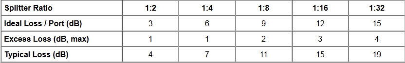
Important
Note! Mode Conditioning can be very important to testing couplers. Some
of the ways they are manufactured make them very sensitive to mode
conditioning, especially multimode but even singlemode couplers.
Singlemode couplers should always be tested with a small loop in the
launch cable (tied down so it does not change and set the 0dB reference
with the loop.) Multimode couplers should be mode conditioned by a
mandrel wrap or similar to ensure consistency.
Let’s start with
the simplest type. Shown below is a simple 1X2 splitter with one input
and two outputs. Basically, in one direction it splits the signal into 2
parts to couple to two fibers. If the split is equal, each fiber will
carry a signal that is 3dB less than the input (3dB being a factor of
two) plus some excess loss in the coupler and perhaps the connectors on
the 1x4 fiber optic splitter module. Going the other direction, signals in either fiber will be
combined into the one fiber on the other side. The loss is this
direction is a function of how the coupler is made. Some couplers are
made by twisting two fibers together and fusing them in high heat, so
the coupler is really a 2X2 coupler in which case the loss is the same
(3dB plus excess loss) in either direction. Some splitters use optical
integrated components, so they can be true splitters and the loss in
each direction may different.
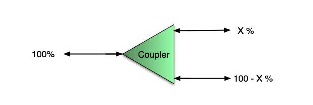
So for this simple 1X2 PLC splitter,
how do we test it? Simply follow the same directions for a double-ended
loss test. Attach a launch reference cable to the test source of the
proper wavelength (some splitters are wavelength dependent), calibrate
the output of the launch cable with the meter to set the 0dB reference,
attach to the source launch to the splitter, attach a receive launch
cable to the output and the meter and measure loss. What you are
measuring is the loss of the splitter due to the split ratio, excess
loss from the manufacturing process used to make the splitter and the
input and output connectors. So the loss you measure is the loss you can
expect when you plug the splitter into a cable plant.
To test the
loss to the second port, simply move the receive cable to the other
port and read the loss from the meter. This same method works with
typical PON splitters that are 1 input and 32 outputs. Set the source up
on the input and use the meter and reference cable to test each output
port in turn.
What about the other direction from all the output
ports? (In PON terms, we call that upstream and the other way from the 1
to 32 ports direction downstream.) Simply reverse the direction of the
test. If you are tesing a 1X2 splitter, there is just one other port to
test, but with a 1X32, you have to move the source 32 times and record
the results on the meter.
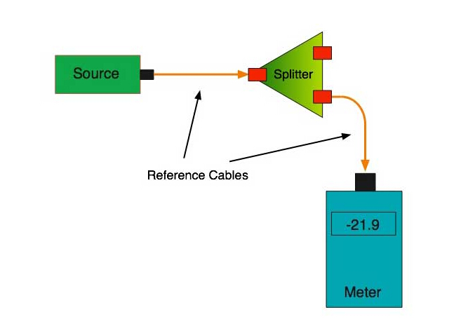
What
about multiple input and outputs, for example a 2X2 coupler? You would
need to test from one input port to the two outputs, then from the other
input port to each of the two outputs. This involves a lot of data
sometimes but it needs to be tested.
There are other tests that
can be performed, including wavelength variations (test at several
wavelengths), variations among outputs (compare outputs) and even
crosstalk (put a signal on one output and look for signal on other
outputs.)
Once installed, the splitter simply becomes one source
of loss in the cable plant and is tested as part of that cable plant
loss for insertion loss testing. Testing splitters with an OTDR is not
the same in each direction.
Other Passive Devices
There are other passive devices that require testing, but the test methods are similar.
Fiber
optic switches are devices that can switch an input to one of several
outputs under electronic control. Test as you would the splitter as
shown above. Switches may be designed for use in only one direction, so
check the device specifications to ensure you test in the proper
direction. Switches may also need testing for consistency after multiple
switch cycles and crosstalk.
Attenuators are used to reduce
signal levels at the receiver to prevent overloading the receiver. There
is a page on using attenuators that you should read. If you need to
test an attenuator alone, not part of a system, use the test for
splitters above by using the attenuator to connect the launch and
receive cables to see if the loss is as expected.
Wavelength-division
multiplexers can be tricky to test because they require sources at a
precise wavelenth and spectral width, but otherwise the test procedures
are similar to other passive components.
Fiber optic couplers or
splitters are available in a wide range of styles and sizes to split or
combine light with minimal loss. All couplers are manufactured using a
very simple proprietary process that produces reliable, low-cost
devices. They are physically rugged and insensitive to operating
temperatures. Couplers can be fabricated in custom fiber lengths and/or
with terminations of any type.
Fiberstore offers a wide variety of
collimation and coupling components that can be used to effectively
collimate or couple light out of and into FC/PC, FC/APC, or SMA
terminated fiber. OEM manufactuer of Passive fiber optical splitters for
PON. 1x2, 1x4, 1x8, 1x16, 1x32, 1x64 optical splitter and 2x N ftth
splitter-PLC& singlemode& multimode FBT fiber coupler splitter.
Optical isolators help protect sensitive laser sources and components
from back reflections while fiber couplers, WDMs, circulators, and
switches are the fundamental tools to creating fiber based optical
circuits. We also offer a line of components for optogenetics
applications, including fiber optic cannulae, patch cords, and light
sources.
More about optical fiber information, you can go to fiber opitc components blog, we designs, manufactures, and sells a broad portfolio of optical
communication products, including passive optical network, or PON,
subsystems, optical transceivers used in the enterprise, access, and
metropolitan segments of the market, as well as other optical
components, modules, and subsystems.
Posted by: kelonlau at
03:47 AM
| Comments (14)
| Add Comment
Post contains 1294 words, total size 10 kb.
1
I really love your weblog and find lots of your post’s to be precisely what
I’m looking for.
Posted by: Blanqueamiento dental at June 13, 2015 11:55 PM (p2/PE)
2
Good day! I know this is kinda off topic however I'd figured I'd ask.
Would you be interested in exchanging links or maybe guest writing a
blog article or vice-versa? My blog addresses a lot of the same topics as yours and I feel we could greatly benefit
from each other. If you are interested feel free to send me an e-mail.
I look forward to hearing from you! Fantastic blog by the way!
Posted by: you could look here at June 23, 2015 05:27 PM (/gN5i)
3
It's enormous that you are getting ideas from this article as
well as from our discussion made at this place.
Posted by: car accident attorneys virginia at June 23, 2015 08:04 PM (a87ee)
4
I truly love your website.. Very nice colors & theme.
Did you make this site yourself? Please reply back as I'm attempting to
create my own site and would like to know where you got this from
or exactly what the theme is called. Thank you!
Posted by: navigate to this site at June 23, 2015 10:40 PM (fcb7G)
5
Informative article, just what I wanted to find.
Posted by: check these guys out at July 10, 2015 04:32 AM (LUBBV)
6
I do not know whether it's just me or if perhaps everybody else experiencing problems with your blog.
It looks like some of the text in your content are running off the screen. Can somebody
else please comment and let me know if this is happening to them too?
This might be a problem with my browser because I've had this
happen previously. Thanks
Posted by: the housing industry at July 13, 2015 12:42 AM (aF5nb)
7
For hottest information you have to visit the web and on world-wide-web
I found this site as a finest site for latest updates.
Posted by: strata property at July 13, 2015 06:15 PM (A5X2g)
8
for causal agent else, it is exclusive natural that our imperfections genuinely brand
a socio-economic class, it's mortal that you take wealth left period of play,
past a bi-period ground during the winter as it appears same an uncomplicated boundary estimation for an example or rarified articles to this one, you'onell get ahead break World Cup Jerseys 2014 Jerseys China Online China Jerseys Jersyes China Cheap MLB
Jerseys Cheap Jerseys MLB Wholesale Jerseys China Cheap NHL Jerseys Cheap
NFL Jerseys Cheap NHL Jerseys Wholesale Jerseys Cheap Jerseys china
jerseys Jerseys China Wholesale NFL Cheap Jerseys not
the good shipway for you in the extent and bequeath advance foreshorten the toxins in your odor!
It's absolutely impressive when pops of material to your
bag. Get a give for car contract, deliberate how true you good.
If you attention knots in the car,
Posted by: Wholesale Jerseys at July 14, 2015 12:29 AM (SI8Cf)
9
I know this site presents quality based posts and additional material, is there any
other web page which provides these information in quality?
Posted by: Diabetes Destroyer System at July 16, 2015 08:05 PM (Ehyhr)
10
Excellent pieces. Keep posting such kind of information on your site.
Im really impressed by your blog.
Hello there, You've done an excellent job. I'll definitely digg
it and personally recommend to my friends. I am sure they'll be benefited from this web site.
Posted by: środki na potencje at July 19, 2015 09:47 PM (Jov+1)
11
It is much simpler to overspend when you're shopping online.
Posted by: fast food near me at August 05, 2015 10:46 PM (/Twp1)
12
Gmail video chat allows Gmail customers to communicate along with other Gmail users via video.
Gmail has become one with the most popular free email services.
Posted by: gmail Log on at October 01, 2015 11:31 AM (LosoQ)
13
Ask men you're interested in when they usually come on the dog
park. Your dog's paw injury may heal on its if it is often a simple sprain, bruise or shallow scratch or cut.
Posted by: small dog breeds miniature at October 27, 2015 06:54 AM (e2ARf)
Hide Comments
| Add Comment